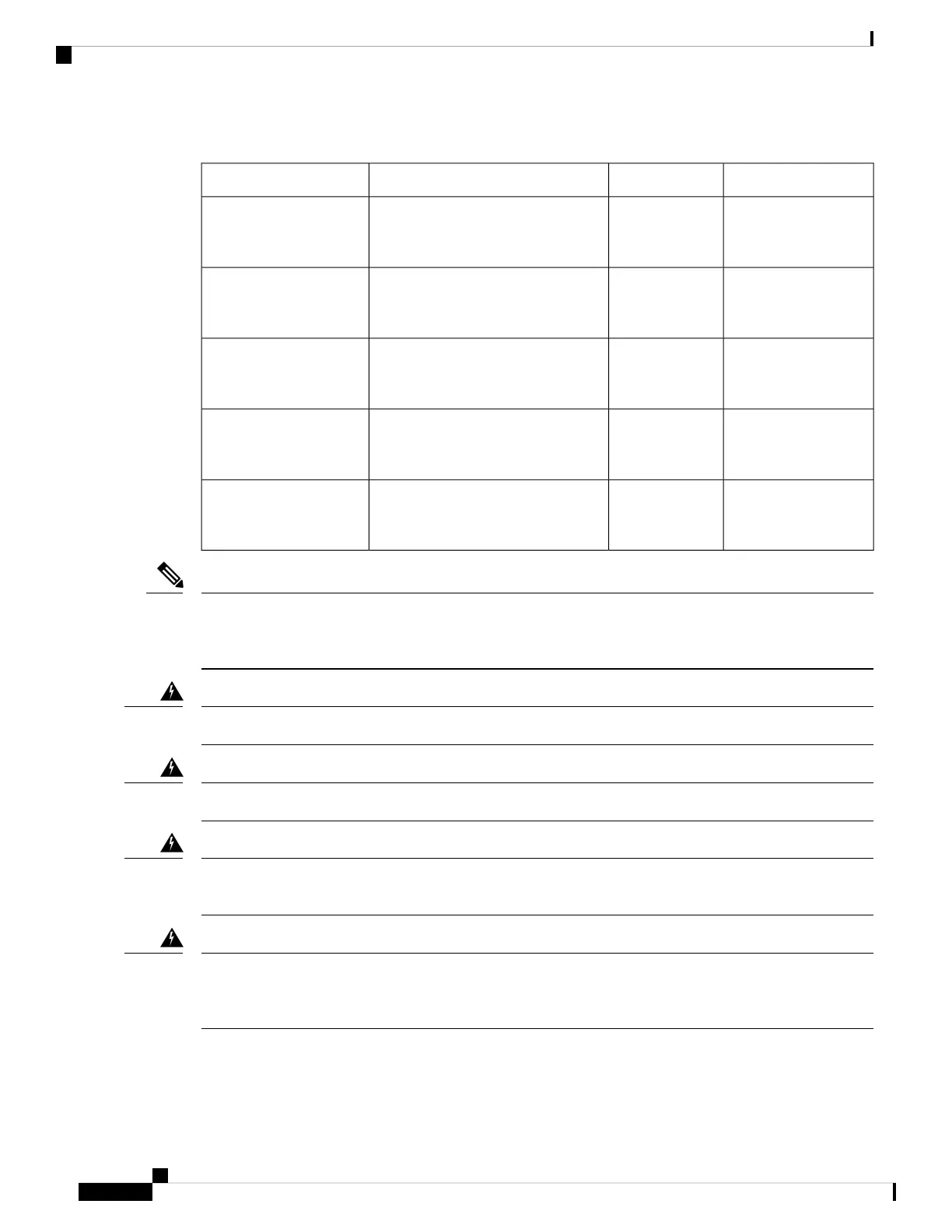
Table 1: Zero-RU PDU Descriptions
CountryPlugDescriptionProduct ID
North AmericaL6-30P30 A, metered input, single-phase,
vertical-mount PDU with 6 C19 and
36 C13 connectors
RP208-30M1P-6-36
North AmericaL15-30P30 A, metered input, three-phase,
vertical-mount PDU with 6 C19 and
30 C13 connectors
RP208-30M3P-6-30
North AmericaIEC60309 460P960 A, metered input, three-phase,
vertical-mount PDU with 12 C19 and
9 C13 connectors
RP208-60M3P-12-9
InternationalIEC60309 332P632 A, metered input, single-phase,
button-mount (rear and sides) PDU
with 6 C19 and 36 C13 connectors
RP230-32M1P-6-36
InternationalIEC60309 532P632 A, metered input, three-phase,
button-mount (rear and sides) PDU
with 12 C19 and 12 C13 connectors
RP230-32M3P-12-12
The RP208-60M3P-12-9 PDU must be installed in the rear facing locations as shown in Figure 5: One Zero-U
PDU Installed on the Rear-Facing Flange, on page 6. The increased size of this PDU requires the rear-facing
installation to avoid interference with equipment and cabling.
Note
No serviceable parts inside. To avoid risk of electric shock, do not open.
Warning
Read the installation instructions before using, installing or connecting the system to the power source.
Warning
This product relies on the building’s installation for short-circuit (overcurrent) protection. To reduce risk of
electric shock or fire, ensure that the protective device is rated not greater than:
Warning
This equipment must be grounded. To reduce the risk of electric shock, never defeat the ground conductor or
operate the equipment in the absence of a suitably installed ground conductor. Contact the appropriate electrical
inspection authority or an electrician if you are uncertain that suitable grounding is available.
Warning
Installing Cisco RP-Series PDUs
2
Installing Cisco RP-Series PDUs
Installing a Zero-U PDU
 Loading...