Installing the Lower and Upper Display Frames
© 2015 Cisco Systems, Inc. All rights reserved.
P a g e 11
5
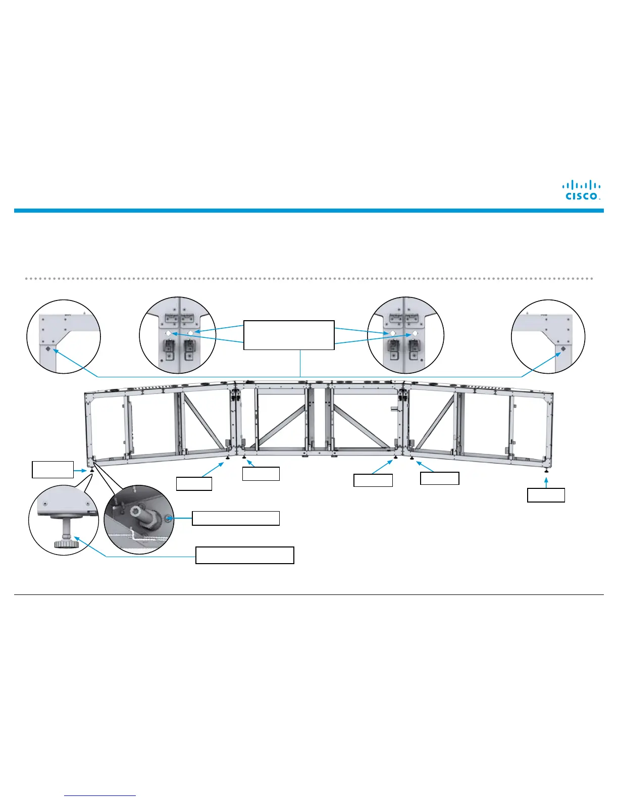
Level the system end-to-end using a laser level. Use the diamond-shaped leveling marks as a guide for the
horizontal level. Note: When leveling the system, use the outside feet of the two outside display frames (Foot
A in the illustration) and both feet of the center display frame (Foot C in the illustration). Loosen the 19mm lock nut
on the leveling feet, and adjust the feet using the 13mm hex profile above each foot.
Foot C
Foot B
19mm Lock nut
Foot A
Diamond-shaped
leveling mark
Foot C
Foot B
Foot A
13mm hex profile
 Loading...