10
Fasten left monitor and connect power cable
78-100254-03A0 | 2016 JUNE | © 2016 Cisco Systems, Inc. All rights reserved.
Page 14
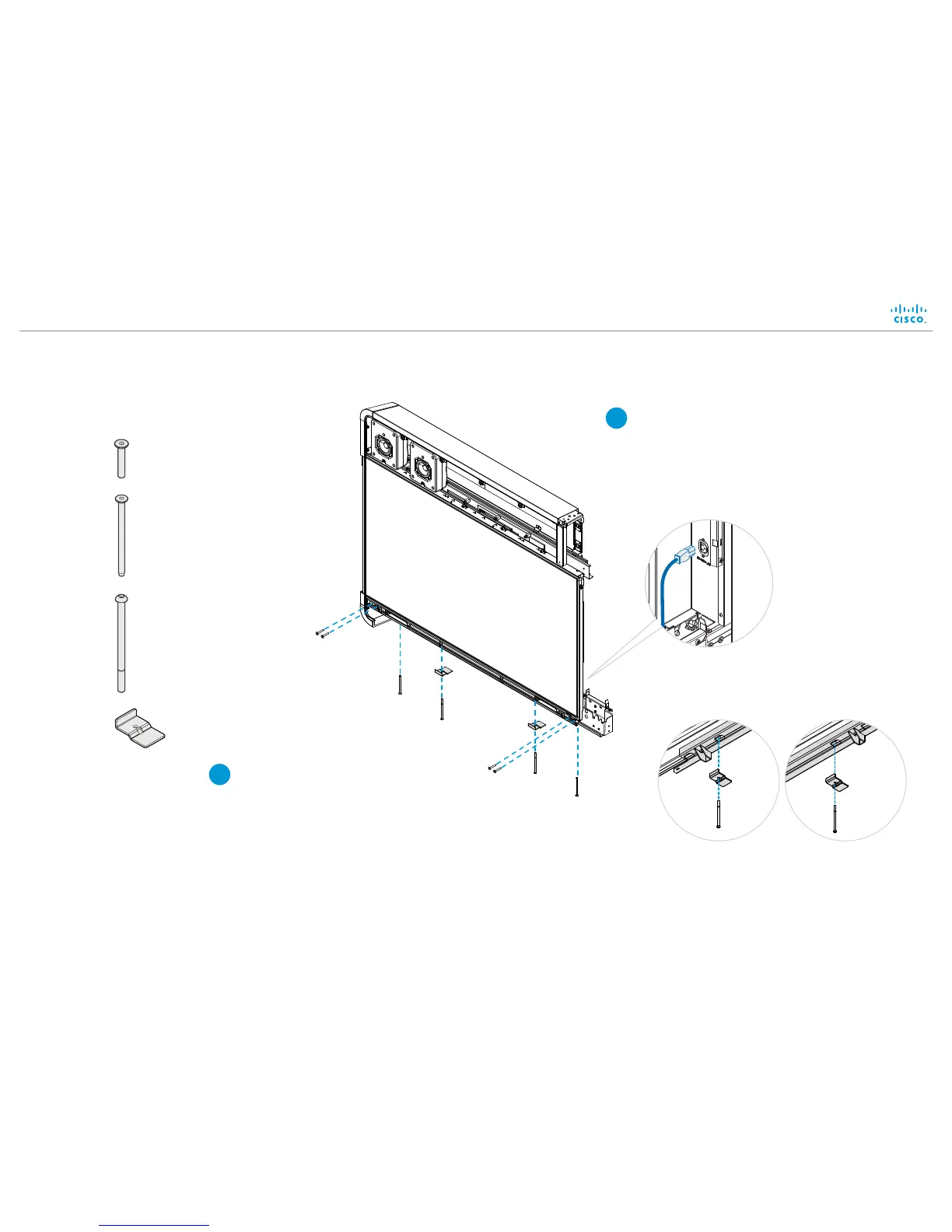
Connect power cable
A power cable is strapped at the rear of the
monitor. Connect it to the close-by socket.
Let the other end hang freely. It will be
connected to the right monitor in step 12.
2
Rear view
Enter the following screws:
• Four M6x35 screws, from front.
• Two M6x90 screws, from underneath.
• Two M6x100 screws and their brackets, from
underneath.
Then, tighten all screws.
1
2 × M6x90, countersunk
4 ×
M6x35, countersunk
2 ×
M6x100, pan
2 ×
Bracket
Right side of the
monitor, viewed
from underneath
Left side of the
monitor, viewed
from underneath
 Loading...