23
Connect external cables (page 1 of 2)
I, J
78-100254-03A0 | 2016 JUNE | © 2016 Cisco Systems, Inc. All rights reserved.
Page 28
Network
1
Microphones
(max 8)
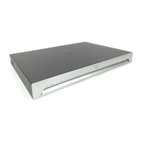
Codec connector panel
Power (100-240 VAC, 50/60 Hz),
extension cord, and country-specific cables
Video input,
for example
computer
(max 2)
2
Make sure that the camera can move
freely before connecting power.
Route the cables along
the lower frame, and place
them in the cable bridge.
1
CAT 5e, shielded Ethernet cable, 5 m.
2
Two presentation cables are provided: HDMI ↔ HDMI;
and DVI/Euroblock ↔ VGA/mini jack.
Always use the power
cables provided.
The plug-socket
combination must always
be accessible, because
it serves as the main
disconnecting device.
 Loading...
