Temp. Sensor
Pt1000
T4A
100 ... 240 V~
50-60 Hz
1 (1) A (100 ... 240) V~
2 (1) A (100 ... 240) V~
R1-R3
R4
L
R3
R2
R1
GND
S1
S2
S3
S4
S5
VBus
PWM 1
PWM 2
N
R4
V40
L'
VFS
RPS
CU 72102083.01
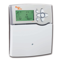
DeltaSol BX
®
Made in Germany
IP 20
The controller is supplied with power via a mains cable.
The power supply of the device must be 100 ... 240 V~
(50 ... 60 Hz).
The controller is equipped with 4 relays in total to which
loads such as a pump, a valve, etc. can be connected:
• Relays R1 ... R3 are semiconductor relays, designed for
pump speed control
Conductor R1... R3
Neutral conductor N
Ground terminal
• Relay 4 is a standard relay
Conductor R4
Neutral conductor N
Ground terminal
Depending on the product version, mains cable and sensor
cables are already connected to the device. If that is not the
case, please proceed as follows:
Connect the temperature sensors (S1 to S5) to the
corresponding terminals with either polarity:
S1 = sensor 1 (collector sensor )
S2 = sensor 2 (e. g. store sensor base)
S3 = sensor 3 (e. g. store sensor top)
S4 = sensor 4 (e. g. store sensor store 2)
S5 = sensor 5 (e. g. collector sensor collector 2)
Connect the Grundfos sensors to the VFS and RPS inputs.
A V40 flowmeter can be connected to the terminals V40
and GND (either polarity).
The terminals marked “PWM” are control outputs for a
high-efficiency pump (PWM1 is allocated to R1 and PWM2
is allocated to R2).
The mains connection is at the terminals:
Neutral conductor N
Conductor L
Conductor L' (L' is not connected with the mains cable. L'
is a fused contact permanently carrying voltage)
Ground terminal
WARNING! Electric shock!
Upon opening the housing, live parts
are exposed.
Î Always disconnect the control-
ler from power supply before
opening the housing!
Note:
Connecting the device to the power supply must
always be the last step of the installation!
Note:
For more details about the initial commissioning
procedure, see chap. 5, page 13.
WARNING! Electric shock!
L' is a fused contact permanently
carrying voltage
Î Always disconnect the control-
ler from power supply before
opening the housing!
 Loading...