U
The Citroën Guide Brakes: Anti-lock Braking System 45
Anti-lock Braking System
Models with higher performance level came fitted
with ABS.
The principle of operation is the same as on cars with con
-
ventional braking systems but the layout is much simpler as
all we need to control the operating pressure of the brakes
are a few electro-valves.
During breaking, the ABS computer monitors the
changes in the rotational speed of each roadwheel, commu
-
nicated by inductive magnetic sensors reading the individ
-
ual cogs of a toothed wheel fitted inside the cavity of the
brake discs. The computer does not interfere with the brak
-
ing if the vehicle speed (as measured with the same sen
-
sors) is below 5 km/h.
If any of the wheels begins to slow at a faster rate than
the others, the ABS reduces the hydraulic pressure fed to
the brake caliper of the wheel in question to avoid the
wheel being locked. Although every wheel has its own sen
-
sor, the rear brake calipers receive the same pressure, only
the front ones are fed separately. As soon as road grip is re
-
gained, the hydraulic pressure to the brake will be restored.
The computer is capable of cycling the pressure with a fre
-
quency of several times a second.
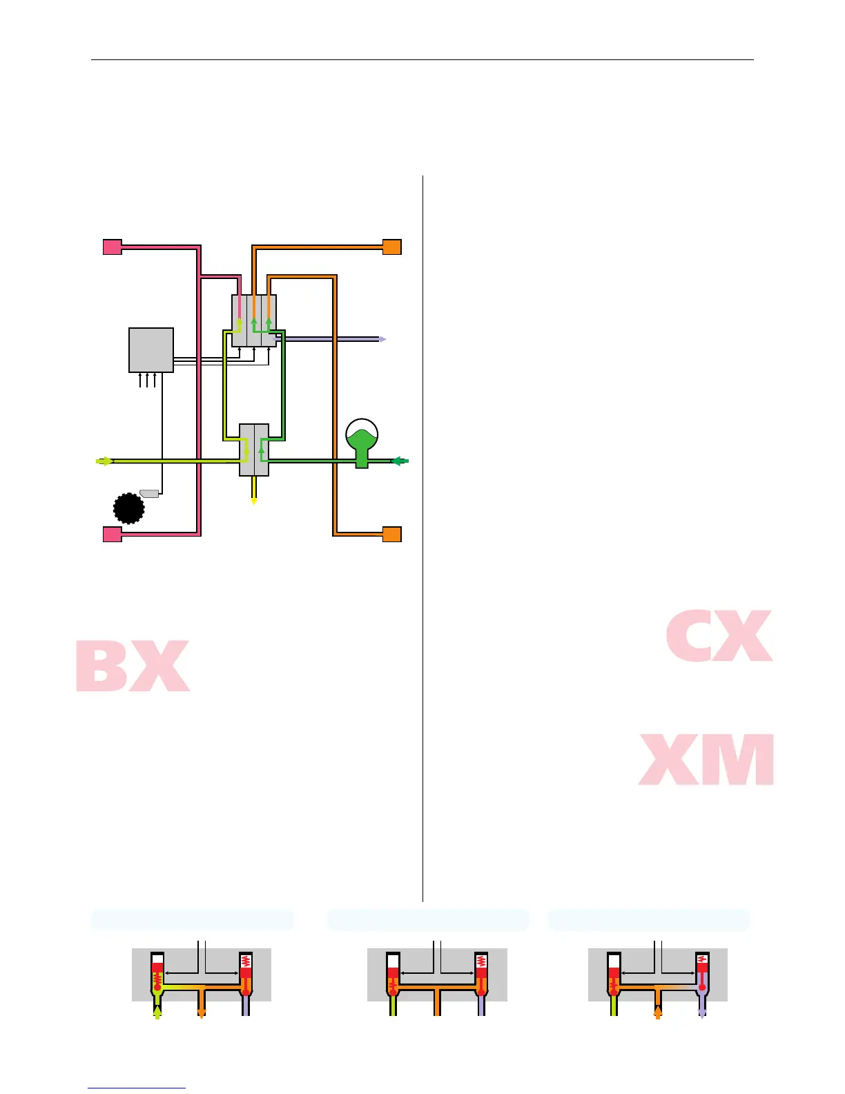
To actually control the pressure, the system uses a three-
unit hydraulic block (one block each for the front brakes,
one for both rear brakes). All three units comprise two elec
-
tro-valves, an inlet 1 and a return 2 valve.
During the rising period of normal braking, without the
need for the intervention of the ABS computer, the brakes
operate in phase 1: the inlet valve 1 is open but the return
valve 2 is closed. The braking functions as in a system with
-
out ABS: the incoming hydraulic pressure is directly routed
to the brake caliper.
Under constant breaking (phase 2) both valves close to
maintain a steady hydraulic pressure in the brake calipers.
When the ECU senses the need for intervention, the elec
-
tro-valves proceed to phase 3: the inlet valve 1 closes
while the return valve 2 closes. Hydraulic pressure will be re
-
leased from the brake caliper, reducing the braking force.
To restore the braking effort, the ECU will return to phase 1
in a short while.
The ABS computer has a built-in diagnostic feature,
checking the components both when the ignition is turned
on and during braking. Any failure will be reported by a
warning lamp or a warning message of the board com
-
puter. As you can see from the illustration, the springs in
-
side the valves are located in such a way that the mechani-
cal default mode is phase 1—the normal braking—for all
three hydraulic blocks. Any failure in the ABS system will
therefore revert it to the usual, non-assisted braking.
Early CXs has a slightly different ABS system. The general
layout is the same, but the hydraulic block only has three
valves, one for each brake circuit, however, they have three
positions. Without energizing current, they route the fluid
coming from the brake accumulator to the brakes. In phase
2, a medium current switches them to isolate the brake cali
-
pers, while a larger current opens it completely to let the
pressure escape from the brakes into the return lines.
On XM the hydraulic block has five electro-valves only. I
am not sure how they connect internally, but I suspect that
the valve that closes supply for the front brakes is common
for the left and right wheel ???

 Loading...


