CD037RMP
-3-
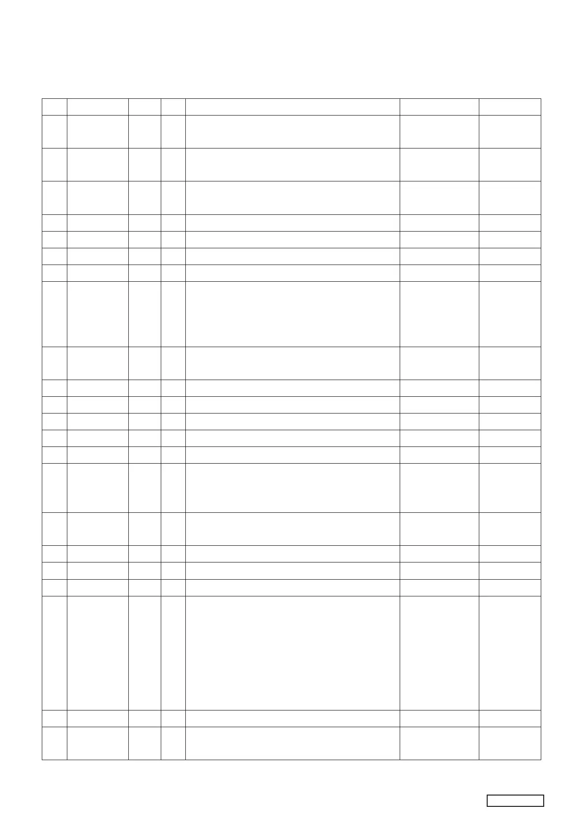
PIN P-NAME I/O Act DESCRIPTION When not Used REMARK
19 VR CLK O E.VR Communication CLK OUT
Needed pull up resistor(2.2K) from switch 5Vdc.
Open Open
DRAIN
20 VR DATA O E.VR Communication DATA OUT
Needed pull up resistor(2.2K) from switch 5Vdc.
Open Open
DRAIN
21 SD_DET
/DIO IN12
I L 1. SD Detection Input.
2. Option diode input 12.
22 F_INH O H FRONT Communication INH output.
23 F_DATA I/O FRONT LCD driver Communication data.
24 F_CLK I/O FRONT and LED driver Communication clock.
25 F_CE O H Front Communication Chip Enable.
26 TEF_SCL
PLL_CLK
/STIN
I/O
O
I
1.Clock output to TEF6606 Tuner
2.PLL IC Communication CLOCK OUT.
3.ST input. Low=Stereo.
Series 2.2Kohm to STIN must be added.
Pull up
27 TEF_SDA
PLL_CD
I/O
O
1.Data out/in to TEF6606 Tuner
2.PLL IC Communication DATA INPUT/OUTPUT
28 PLL_CE O PLL IC Communication CHIP ENABLE
29 LOCAL O H Radio LOCAL output during seek(Loc=High)
30 CDPRST O L Reset the DSP and ASP in CDP. Open
31 CDPO O H At CDP mode H is output.
32 USB_DET I L USB Detection Input
33 REMOCON I Remote control input.
The power supply of Remote receiver is to be
turned off during ACC off.
Pull Down
1M
34 SYSTEM
POWER
O H When radio is power on (High=power on).
This port is to control power on of the system.
35 MUTEOUT O L Mute output for power IC(LOW=MUTE)
36 FEEDF O H FEED Motor Forward in single CDP. Open
37 FEEDR O H FEED Motor Reverse in single CDP. Open
38 CDC BUS
TOUCH_
CLK
I/O CD CHANGER Communication BUS Input
Pull down resistor(1M) should be connected.
A zener diode (5.6V) to GND is recommendable
to protect from a outside surge.
Add series 220ohm to protect port.
Clock in/out from/to Touch Sensor(DT8800)
Pull
Down
Pull Down
1M
39 RDS DATA I RDS Data Input in RDS Model. Pull up
40 {RDS CLK}
I/O H RDS Clock Input GND Pull Down
1M