EasyManua.ls Logo

Clarion PU-2294A - User Manual

Clarion PU-2294A
16 pages
To Next Page IconTo Next Page
Loading...
- 1 -
PU-2294A/B
PU-2325A
Published by Service Dept.
Printed in Japan
Clarion Co., Ltd.
Export Division - 22-3, Shibuya 2-chome, Shibuyaku, Tokyo, 150-8335 Japan Tel: 03-3400-1121
Service Dept.- 50 kamitoda,Toda-shi,Saitama,335-8511 Japan Tel: 048-443-1111 FAX:048-433-6996
298-5761-00
Aug.1999 P
Service Manual
Model
Model
Model
PEUGEOT Automobile Genuine
RDS/FM/MW/LW Radio CD Stereo
PU-2294A
(Genuine No. 96 346 766 80)
PU-2325A
(Genuine No. 96 373 095 80)
CITROEN Automobile Genuine
RDS/FM/MW/LW Radio CD Stereo
PU-2294B
(Genuine No. 96 346 767 80)
SPECIFICATIONS
Radio section
Tuning system: PLL frequency synthesizer system
Receive range: FM 87.5MHz to 108.0MHz
MW 531kHz to 1,602kHz
LW 153kHz to 279kHz
Intermediate frequency:
FM 10.7
±0.2MHz
MW 450
±3kHz
LW 450
±3kHz
Quieting sensitivity: FM Less than 13dB
μ(30dB S/N)
MW Less than 36dB
μ(20dB S/N)
LW Less than 43dB
μ(20dB S/N)
Separation: FM More than 20dB
Auto tuning stop sensitivity:
FM 22
±8dBμ(DX)
45
±10dBμ(LO)
MW30
±10dBμ(DX)
60
±10dBμ(LO)
LW 30
±10dBμ(DX)
60
±10dBμ(LO)
CD player section
Separation: More than 65dB
S/N ratio: More than 80dB
Distortion: Less than 1.0
General
Load impedance: 4Ω
Output power: More than 10W×4
Power supply voltage: DC13.5V
Negative ground
Current consumption: Less than 10A
Dimensions(mm): 178(W)
×50(H)×165(D)
Weight: 1.45kg
Specifications and design are subject to change without
notice for further improvement.
COMPONENTS
PU-2294A-A/PU-2294B-A/PU-2325A-A
Main unit −−−−− 1
NOTE
We cannot supply PWB with component parts in prin-
ciple. When a circuit on PWB has failure , please repair
it by component parts base. Parts which are not men-
tioned in service manual are not supplied.
PU-2294A/B
PU-2325A
To engineers in charge of repair or
inspection of our products.
Before repair or inspection, make sure to follow
the instructions so that customers and Engineers
in charge of repair or inspection can avoid suf-
fering any risk or injury.
1. Use specified parts.
The system uses parts with special safety features against
fire and voltage. Use only parts with equivalent charac-
teristics when replacing them.
The use of unspecified parts shall be regarded as re-
modeling for which we shall not be liable. The onus of
:
Question and Answer IconNeed help?

Do you have a question about the Clarion PU-2294A and is the answer not in the manual?

Clarion PU-2294A Specifications

General IconGeneral
BrandClarion
ModelPU-2294A
CategoryStereo System
LanguageEnglish

Summary

Product Identification and Specifications

PEUGEOT;CITROËN Radio CD Stereo Models

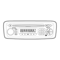
Identifies specific PEUGEOT and CITROËN radio CD stereo models.

Radio Section Specifications

Details radio tuner specifications, including tuning system and receive ranges.

CD Player Section Specifications

Details CD player specifications like separation and S/N ratio.

General Specifications

Lists general technical specifications for the unit.

Components Overview

Main Unit Components

Lists the main unit components for specific models.

Printed Circuit Board (PWB) Policy

Clarifies the policy on supplying PWB component parts.

Repair and Inspection Guidelines

Use of Specified Parts

Emphasizes using specified parts for safety and to avoid liability.

Wiring and Part Placement

Instructs on correct wiring and part placement after repair.

Post-Repair Safety Checks

Advises thorough safety checks after completing repairs.

Automotive Wiring Precautions

Warns about battery disconnection and fire hazards during automotive wiring.

Component Handling Cautions

Advises on handling chips, particularly tantalum capacitors.

Flexible PWB Soldering Guidelines

Provides guidelines for soldering flexible PCBs, including temperature.

Unit Operation During Disassembly

Instructs to turn off the unit before disassembly and recheck work.

Optical Pickup Laser Precautions

Advises eye safety distance from optical pickup laser.

Optical Pickup Handling

Warns about electrostatic discharge damaging the optical pickup.

Laser Diode and Actuator Notes

Details laser diode terminal shorting and actuator magnetic circuit.

Optical Lens Cleaning

Describes cleaning the optical lens with isopropyl alcohol.

Class 1 Laser Product Warning

Laser Safety and Service

Warns about Class 1 Laser Product safety and service contact.

Computer Anti-Theft System (CATS)

CATS Release Procedure

Explains the steps to release the Computer Anti-Theft System.

Adjustments and Block Diagram

FM S-meter Adjustment

Details the procedure for adjusting the FM S-meter.

System Block Diagram

Illustrates the overall system architecture.

Microcontroller (μPD784216 BGC) Pinout

Explains the function of each pin of the microcontroller.

Terminal Descriptions

Lists and describes the function of various terminals.

Technical Data Tables

Diagnosis Phantom Signal Output

Shows output values for diagnosis phantom signal.

Destination Select Input

Lists destination select inputs for different regions.

Loading Motor Control Signals

Details loading motor control signal outputs.

Digital Signal Processor (TC9462 F) Details

TC9462 F Form and Function

Describes the TC9462F's outward form and primary functions.

TC9462 F Terminal Descriptions

Provides a detailed description of each TC9462F terminal.

TC9462 F Pin Functionality

Explains the specific function of each pin on the TC9462F.

Microcontroller Pinout Details

Microcontroller Pin Functions (Continued)

Continues the detailed description of microcontroller pin functions.

Playback Speed Flag Table

Shows playback speed flag data.

Exploded View and Parts List

Main Section Exploded View

Displays an exploded view of the main unit assembly.

Main Section Parts List

Lists the part numbers and descriptions for the main section.

CD Mechanism Parts List (Section 1)

CD Mechanism Drive Unit Components

Lists parts related to the CD mechanism's drive unit.

CD Mechanism Linkage and Support Parts

Lists parts like link assemblies, plates, and holders.

CD Mechanism Pickup and Motor Parts

Lists parts including pickup units, motors, and related components.

CD Mechanism Parts List (Section 2)

CD Mechanism Plate and Bracket Parts

Lists various plates and brackets for the CD mechanism.

CD Mechanism Gear and Roller Parts

Lists gear and roller components used in the CD mechanism.

CD Mechanism Roller Shaft and Damper Parts

Lists roller shafts and damper parts for the CD mechanism.

CD Mechanism Parts List (Section 3)

CD Mechanism Spring and Wire Components

Lists various springs and wires for the CD mechanism.

CD Mechanism Motor and PWB Components

Lists motor assemblies and Printed Wiring Boards.

Electrical Parts Lists Overview

Main PWB Section (B1)

Lists electrical components for the Main PWB.

Switch PWB Section (B2)

Lists electrical components for the Switch PWB.

ISO PWB Section (B3)

Lists electrical components for the ISO PWB.

CD Mechanism PWB Section (B4)

Lists electrical components for the CD Mechanism PWB.

Component Electrical Parts List (Part 1)

Integrated Circuits (ICs)

Lists various Integrated Circuits with part numbers.

Inductors (L) and Connectors (P)

Lists Inductors and Connectors with part numbers.

Transistors (Q) and Resistors (R)

Lists Transistors and Resistors with part numbers.

Support Components (SUP, TH)

Lists support components like SUP and TH with part numbers.

Component Electrical Parts List (Part 2)

Oscillators (X) and Switches (S)

Lists Oscillators and Switches with part numbers.

Capacitors (C) and Diodes (D)

Lists Capacitors and Diodes with part numbers.

Integrated Circuits (ICs) and Inductors (L)

Lists ICs and Inductors with part numbers.

Transistors (Q) and Resistors (R)

Lists Transistors and Resistors with part numbers.

Circuit Diagrams

ISO PWB Section Circuit Diagram

Presents the circuit diagram for the ISO PWB section.

Connector Pinout Descriptions

Lists and describes the pin functions for connectors.

Printed Wiring Board Layouts

Main PWB and ISO PWB Layouts

Shows the printed wiring board layouts for Main and ISO PWBs.

Connector Pinout Diagrams

Illustrates the pinout diagrams for various connectors.

Printed Wiring Board Layouts (CD Mechanism)

Switch PWB Layout

Shows the printed wiring board layout for the Switch PWB.

CD Mechanism PWB Layouts

Displays printed wiring board layouts for CD mechanism sections.

Motor and PWB Identification

Identifies motors and Printed Wiring Boards for the CD mechanism.

Related product manuals