Section 7. Planned Maintenance and Lubrication
Major Component Locations 7-9
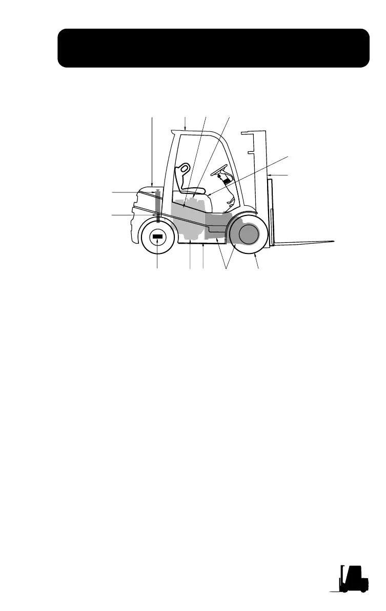
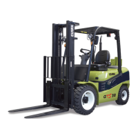
Major Component Locations
Use the illustration below to help locate components included in the
PM procedures.
The truck shown above is a typical representation of a Clark internal
combustion lift truck. Your model may vary slightly.
1
2
3
4
5
6
7
8
9
10
11
12
13
1. Radiator
2. Transmission Cooler
(C20-35)
3. Frame
4. Steer Axle
5. Engine
6. Transaxle
7. Wheels and Tires
8. Counterweight
9. Overhead Guard
10. Exhaust
11. Carburetion
12. Sheet Metal
13. Upright and Carriage