3
Parts & Service: 020 8988 7400 / E-mail: Parts@clarkeinternational.com or Service@clarkeinternational.com
INVENTORY
Remove all components from the carton and check them against the
following list.
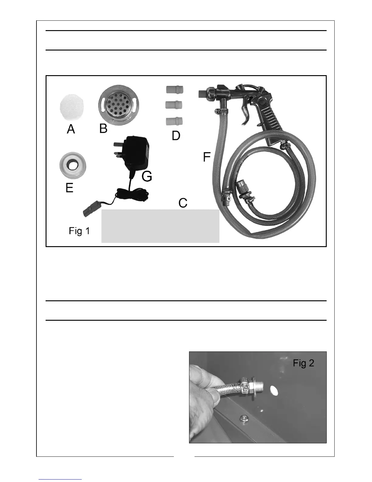
A - Foam Vent Filter B - Air Vent Cover C - 9 x Spare protective film
D - Ceramic Nozzles 4, 5, 6 & 7mm (one nozzle is fitted) E - PTFE tape
F - Gun c/w air and pickup hoses G - 12V transformer & cable
ASSEMBLY
The unit is shipped fully assembled, except for the air vent filter and the gun
with attached hoses. These should be connected as follows:
First, remove the grid and all the
various loose components from within
the cabinet.
The end of the air inlet hose,
connected to the gun, is inserted
through the 16mm dia. hole in the
cabinet from the inside, as shown in
Fig 2. Ensure a flat washer is threaded
on to the adapter as shown.