5
Parts & Service: 020 8988 7400 / E-mail: Parts@clarkeinternational.com or Service@clarkeinternational.com
As the colours of the flexible cable of this appliance may not correspond with
the coloured markings identifying terminals in your plug, proceed as follows:
• Connect GREEN & YELLOW wire to plug terminal marked with a letter “E”
or Earth symbol “ ”, or coloured GREEN or GREEN & YELLOW.
• Connect BROWN wire to plug terminal marked letter “L” or coloured
RED.
• Connect BLUE wire to plug terminal marked letter “N” or coloured
BLACK.
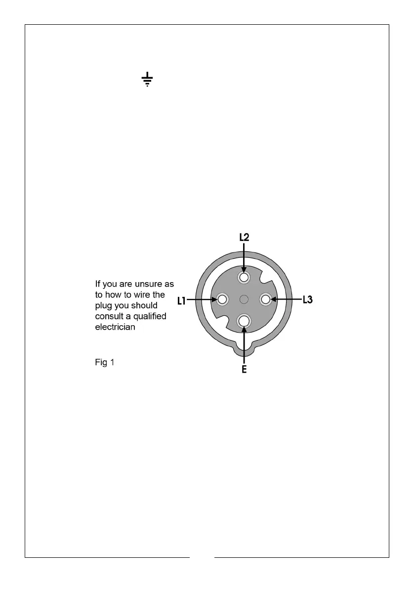
CONNECTING THE OUTPUT
The output is plugged into the socket (E, Fig. 2), using a 4-pin -plug (not
provided). The illustration below shows the socket configuration.
This unit requires a 16A, 400V (3-pin+ earth) plug which should be wired
ensuring pins L1 and L3 are used for the connections across the motor
windings;- i.e. these are the ‘hot phases’.