INSTRUCTIONS
AND
PARTS
' !
DIVISION, ATLAS
PRESS
COMPANY
KALAMAZOO,
MICHIGAN
49001
...
LEVELING
THE
DRILL
PRESS
Drill
press
should
be
level
and
rest solidly
on
Boor; place
~
shims
underneath
the
three
foundation
holes
to
level
the
drill
press. Equal pressure should
be
applied
to founda-
tion
bolts
to
prevent
distorting
the
base.
1661
RAISING HEAD
AND
TA-
BLE
TO
OPERATING
POSITION
1.
To
position
drill
head, loosen
clamp
handle
on
left
side
of
drill
press.
2.
Slide
head
up
column
to
desired
height
and
tighten
clamp handle.
3. Loosen set screw
in
safety collar
and
slide
it
up
column
until
it
touches
bottom
of
head,
then
tighten
set screws.
4.
To
position table, loosen
clamp
handle
on
right
side
of
table.
5. Slide table
up
column
to
desired
height,
and
tighten
clamp
handle.
Generally, the normal and most convenient position
for the
head is about
8"
to 10" from
top
of
column.
IMPORT
ANT:
Always keep safety collar locked
· · under head.
LUBRICATION
Keep
QUILL
(A)
and
COLUMN
(C)
cov-
ered
with
a
light
film
of
oil_:_
see Fig.
(1).
FEED
SHAFT
(B)
grease
weekly
with
No.
1
bearing
grease
- fittings
under
head.
Figure
1
All
bearings
in
the head and lower quill
Me
sealed-
for-life ball bearings and do not require lubrication.
Occasionally
grease spinJle splines.
O~ce
a year, clean
and
grease
(medium
cup
grease) cam
in
ha
ndwheel
(C
, fig. 2
).
To
dis-
assemble
-loosen
screw
(A)
,
and
remove
plate
(B);
re
-
move ha
ndwheel
by
taking
out
center bolt.
Figure
2
1.3
. . I
15"
DRDILl
IPRIESSES
I
I
. i
VARIABLE
.SPEED
DRIVE
MODELS
1660 THROUGH 1793
SERIES-
16VC-
1 - 16VT..; 1
;
FROM
SERIAL
No.
511742
TO
5 5899
JUNE
1965
FILE
NO.
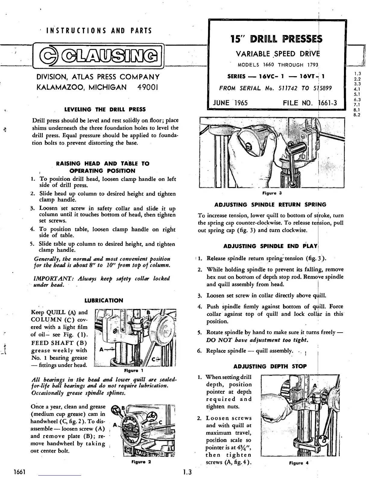
Figure
3
ADJUSTING SPINDLE RETURN
SPRING
To
increase tension,
lower
quill
to
bottom
of
s
~
roke,
turn
the
spring
cap
counter
-
doc~wise.
To
release teAsion,
pull
out
spring
cap (fig:
3)
and
turn
clockwise.
ADJUSTING SPINDLE END PLAY[
' 1. Release
spindle
return
S.pring·tension
(fig.
3).
2.
While
holding
spindle
to
prevent
its
falling
, remove
hex
nut
on
bottom
of
depth
stop
rod.
Remo\re
spindle
and
quill
assembly
from
head. j
3. Loosen
set
screw
in
collar directly above qJill.
4. Push
spindle
firmly
against
bottom
of
q4
ill
. Force
collar against
top
of
quill
and
lock
coll~r
in
this
·
position.
5.
Rotate
spindle
by
hand
to
make
sure
it
turns
freely -
DO
NOT
have
adjustment
too
tight.
6. Replace
spindle
-
quill
assembly. . .
1
ADJUSTING DEPTH
STOP
1.
When
setting
drill
depth,
position
pointer
at
depth
r
equired
and
tighten
nuts.
2.
Loosen
screws
and
with
quill
at
maximum
tr
avel,
po
d
tion
scale
so
pointer
is
at
4%",
then
tighten
screws {A, fig.
4)
.
Figure
4 ·
1.3
2.2
3.3
4. 1
5.1
6.3
7.1
8.1
8.2
 Loading...