Start-up and Calibration (continued)
14
Step 8: The CFH gauge on the front panel of the ozone generator will monitor the CFH air flow rate. By setting the
oxygen concentrator SCFH and ozone generator back pressure PSI, there will be no adjustments of CFH air
flow. See “Air prep system air flow” specifications outlined in Figure 7-1.
Step 9: Perform a final check of all air connections from the air preparation system to the ozone injector manifold.
Repair leaks as required. Check all system water connections, including the ozone injector manifold, vacuum
break and contact vessel. Repair leaks as required. Note: The check valve at the ozone injector manifold
may make a humming noise. This is normal.
Step 10: Reconnect the External Loop connector to the ozone generator. Note: The Ozone LED(s) will not illuminate
until the External Loop has been replaced.
Step 11: Observe all indicating LED(s) on the front cover of the ozone generator. Adjust the manual ozone output
knob to desired level setting.
Vacuum Break
Check the water level in the vacuum break, making sure it is above the flapper valve (see Figure 6-3). If water is not
pressing downward on the flapper valve it will open, causing a loss of vacuum. A loss of vacuum means ozone cannot
flow from the vacuum break, which in turn can cause an ozone leak. Note: If the vacuum break must be refilled with
water disconnect the External Loop from the ozone generator and disconnect the Teflon® ozone delivery line from
the ozone inlet fitting of the vacuum break. This will keep the pressure from the oxygen concentrator from pushing
out the water and shutting down ozone production.
Ozone Destruct System
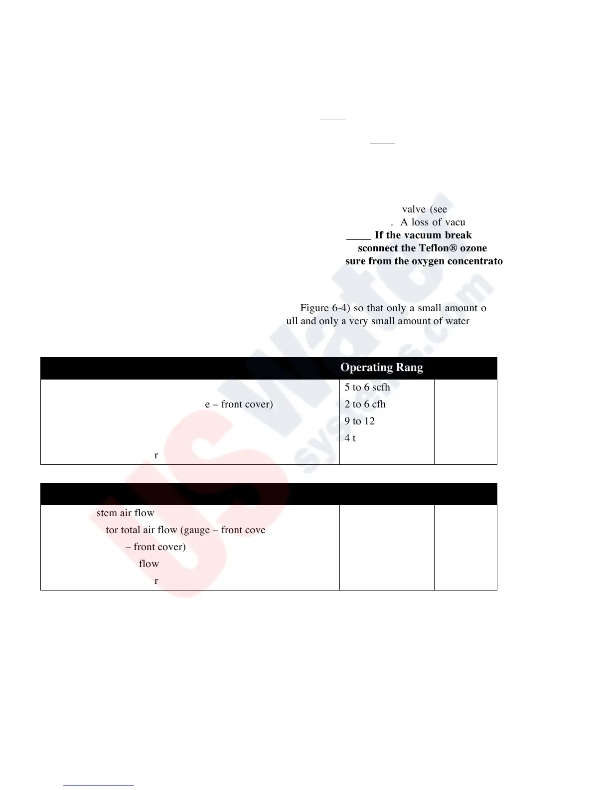
Adjust the small ball valve at the tee of the water trap (see Figure 6-4) so that only a small amount of water is “spitting”
into the trap. This will indicate that the contact vessel is full and only a very small amount of water is allowed to escape.
Pneumatic Operating Parameters Figure 7-1
 Loading...