Maintenance (continued)
16
• Cover Filter: Check the cover filter element mounted on the side of the air preparation system and clean as
required. Operating conditions in the equipment area will dictate the frequency required for this procedure.
Remove the filter element and clean with soap and water, drying them completely before re-installing.
Ozone Generator
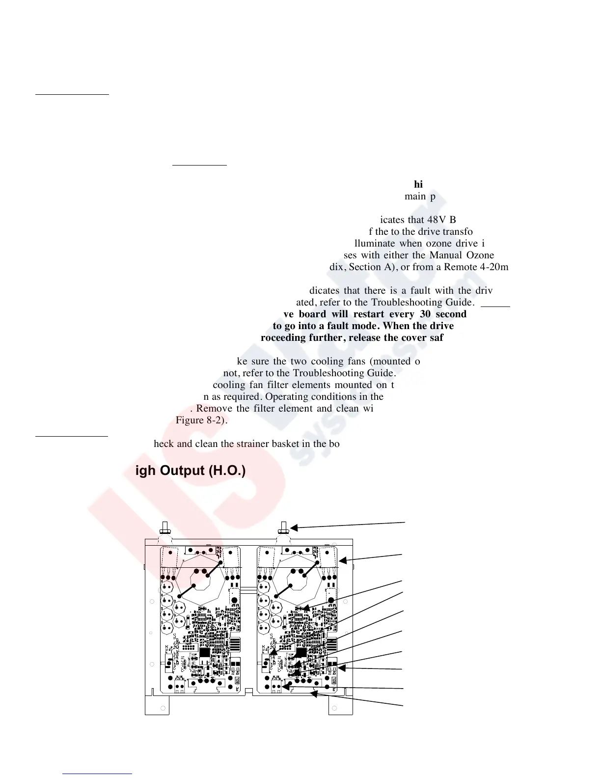
• Drive Module Operation: The Drive Module is made up of two components: the drive board and the drive
transformer. With the ozone generator cover removed, check for illumination of the drive module "Ozone Output"
LED(s) (for LED locations, see Figure 8-1); if not illuminated see Troubleshooting Guide. This procedure is to
observe the complete operating function of the drive module(s). Before checking drive module function, remove
the ozone generator cover and depress the cover safety switch located on the ozone generator chassis (see
Appendix, Section A). CAUTION: This overrides the cover safety switch. The ozone generator will remain
energized with the cover removed. Do not touch anything inside the ozone generator while this switch is
activated! Please consult your ClearWater Tech dealer before attempting this procedure.
- Main Power LED: When illuminated, this “Green” LED indicates that main power is supplied to the drive
module up to the “on board” fuse of the drive board.
- Transformer Power LED: When illuminated, this “Green” LED indicates that 48V Buss power is available to
the drive module transformer (XFMR) from the “on board” fuse of the to the drive transformer.
- Ozone Output LED: The “Amber” ozone output LED will illuminate when ozone drive is being generated.
The LED will also pulse as the output increases or decreases with either the Manual Ozone Output Control
located on the bottom of the ozone generator (see Appendix, Section A), or from a Remote 4-20mA signal (see
“Installation Procedures – Electrical”).
- Fault LED: When illuminated, this “Red” LED indicates that there is a fault with the drive module or the
Ozone Reaction Chamber. If this LED is illuminated, refer to the Troubleshooting Guide. Notes: If the drive
module goes to a fault condition, the drive board will restart every 30 seconds. If the fault is not
remedied the drive module will continue to go into a fault mode. When the drive module is in fault mode
ozone will not be generated. Before proceeding further, release the cover safety switch and replace the
ozone generator cover.
• Cooling Fan Operation: Check to make sure the two cooling fans (mounted on the bottom panel of the ozone
generator cabinet) are operating. If not, refer to the Troubleshooting Guide.
• Cooling Fan Filters: Check the cooling fan filter elements mounted on the bottom of the ozone generator (see
Appendix, Section A) and clean as required. Operating conditions in the equipment area will dictate the frequency
required for this procedure. Remove the filter element and clean with soap and water, drying them completely
before re-installing (see Figure 8-2).
Booster Pump(s)
• Strainer Baskets: Check and clean the strainer basket in the booster pump(s) as required (if so equipped)
Drive Module High Output (H.O.)
Figure 8-1
 Loading...