CB780/CB784 RELAY MODULES
17 32-00207—01
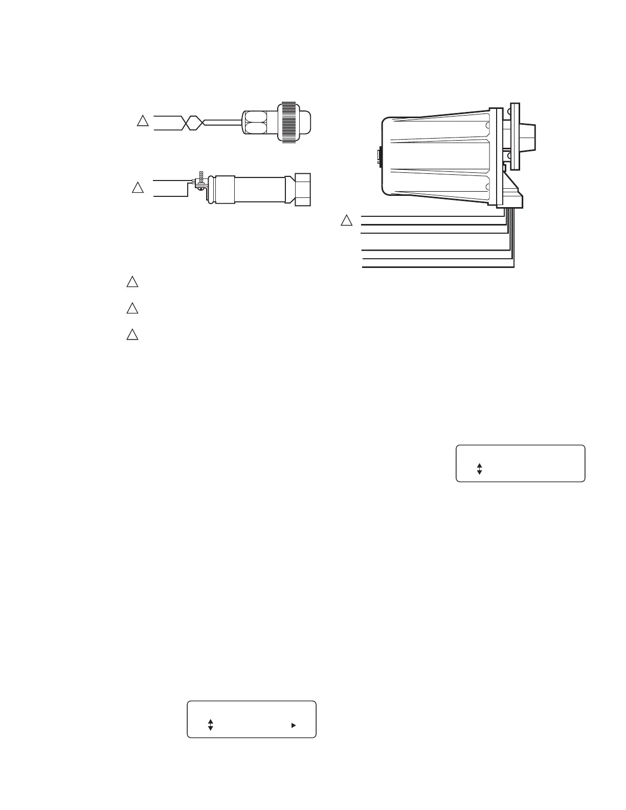
Fig. 16. Flame detector wiring.
OPERATION
Sequence of Operation
The CB780/CB784CB780/CB784 has the following
operating sequence, see Fig. 18 and Table 4.
INITIATE
The CB780/CB784 enters the INITIATE sequence when
the Relay Module is powered. The CB780/CB784 can also
enter the INITIATE sequence if the Relay Module verifies
voltage fluctuations of +10/-15% or frequency
fluctuations of ±10% during any part of the operating
sequence. The INITIATE sequence lasts for ten seconds
unless the voltage or frequency tolerances are not met.
When the tolerances are not met, a hold condition will be
initiated and will be displayed on the VFD for at least five
seconds. When the tolerances are met, the INITIATE
sequence will restart. If the condition is not corrected and
the hold condition exists for four minutes, the
CB780/CB784 will lockout. Causes for hold conditions in
the INITIATE sequence:
1. AC line dropout is detected.
2. AC line noise that can prevent a sufficient reading of
the line voltage inputs.
3. Brownouts caused by a low line voltage.
The INITIATE sequence
also delays the burner
motor starter from being
energized and
de-energized from an
intermittent AC line input
or control input.
STANDBY
The CB780/CB784 is
ready
to start an operating
sequence when the
operating control
determines a call for heat
is present. The burner
switch, limits, operating control and all microcomputer
monitored circuits must be in the correct state for the
CB780/CB784 to continue into the PREPURGE sequence.
NORMAL START-UP PREPURGE
The CB780/CB784 provides a PREPURGE timing
selectable from 30 seconds to 2-1/2 minutes with power
applied and the CB780/CB784 operating control
indicating a call for heat:
Running Interlocks, Preignition Interlocks, Burner Switch,
Run/Test Switch, Lockout Interlocks and all
microcomputer
monitored circuits must be in the correct operating state.
1. The blower motor output, terminal 5, is powered to
start the PREPURGE sequence. The firing rate motor
is driven to the high fire position. The PREPURGE
timing does not begin until the Lockout Interlock
String and High Fire Switch are both closed.
2. The Preignition Interlock input must remain closed
throughout PREPURGE; otherwise, safety shutdown
occurs.
BLUE
YELLOW
WHITE
WHITE
BLACK
BLACK
F
G
22
L2
L1
L2
M27238A
BLUE
WHITE
F
G
F
G
INFRARED (817-1742, 817-4133)
ULTRAVIOLET (817-1743)
SOLID STATE SELF-CHECKING
ULTRAVIOLET (817-1121)
1
2
1
FLAME DETECTOR LEADS ARE COLOR CODED. THE BLUE LEAD MUST BE CONNECTED TO THE F TERMINAL AND THE WHITE
MUST BE CONNECTED TO THE G TERMINAL. THE UV SENSING TUBE IS POLARITY SENSITIVE. REVERSING THE LEADS EVEN
MOMENTARILY CAN DAMAGE OR DESTROY THE UV TUBE.
FLAME DETECTOR LEADS ARE COLOR CODED. THE BLUE LEAD MUST BE CONNECTED TO THE F TERMINAL AND THE YELLOW
MUST BE CONNECTED TO THE G TERMINAL. THE UV SENSING TUBE IS POLARITY SENSITIVE. REVERSING THE LEADS EVEN
MOMENTARILY CAN DAMAGE OR DESTROY THE UV TUBE.
817-1742: 1 BROWN WIRE AND 1 WHITE WIRE FROM THE 817-1742, CONNECT TO THE CB 780/CB 784 WIRING SUBBASE,
COLOR NOT IMPORTANT. 817-4133 1 BLUE WIRE CONNECTED TO THE F TERMINAL AND 1 WHITE WIRE CONNECTED TO
THE GROUND TERMINAL OF THE CB780/784 WIRING SUBBASE. KEEP WIRES AS SHORT AS POSSIBLE AND TWIST THEM.
2
3
3
INITIATE 00:10
Diagnostic Info
M20277A
STANDBY
Total Cycles 132
M20278A