BNP
®
55 SUCTION BLAST CABINET Page 14
© 2019 CLEMCO INDUSTRIES CORP. www.clemcoindustries.com Manual No. 23350, Rev G, 02/19
the dust-collector damper. Refer to the dust-collector
owner’s manual; the damper is located on the inlet on
CDC-1 Dust Collectors, and on the exhauster outlet on
RPC-2 Dust Collectors. If the damper is not opened far
enough, the reclaimer will not remove fines, resulting in
dusty media, poor visibility, and possible media
blockage in the conveying hose. If the damper is opened
too far, it may cause carry over (usable media carried
into the dust collector) and result in excessive media
consumption. Open only as far as necessary to obtain a
balance of dust removal without media carry over.
5.4.3 A manometer is useful when adjusting or
monitoring static pressure. The manometer kit is listed in
Section 9.1: Optional Accessories. Refer to Section 5.8
for manometer operation. The following are static-
pressure starting points for given media. Static pressure
may need to be lower with finer media, higher with
coarser media. Run the media through several blast
cycles, allowing the reclaimer to function with these
settings. Inspect the media in the reclaimer and fines in
the dust collector, as noted in Paragraph 5.4.2. Continue
adjusting static pressure until optimum media cleaning
without carry over is attained.
Glass Bead No. 4 to 7 .................................... 3" – 3-1/2"
Glass Bead No. 8 to 13 .................................... 2-1/2 – 3"
Aluminum Oxide 60-mesh & coarser ..................... 4 – 5"
Aluminum Oxide 80-mesh & finer .................... 2-1/2 – 3"
5.4.4 If the damper has been adjusted and carry over
or excessive dust in the media continues, the optional
externally adjustable vortex cylinder, not available for
300 cfm reclaimers, may help retain media. The vortex
cylinder is usually required only when using 180-mesh
and finer media, or lightweight media. Refer to Section
5.5.
5.5 Optional, Externally Adjustable Vortex
Cylinder
Not available for 300 cfm reclaimer
The externally adjustable vortex is an option when the
cabinet is provided with a CDC-1 Dust Collector. The
vortex is standard with 600 cfm reclaimers when the
cabinet is provided from the factory with an RPC-2 Dust
Collector.
The vortex cylinder fine tunes media separation. Before
adjusting the cylinder, adjust the damper on the dust
collector to increase or decrease static pressure, per
Section 5.4. Once the damper is adjusted, adjust the
cylinder.
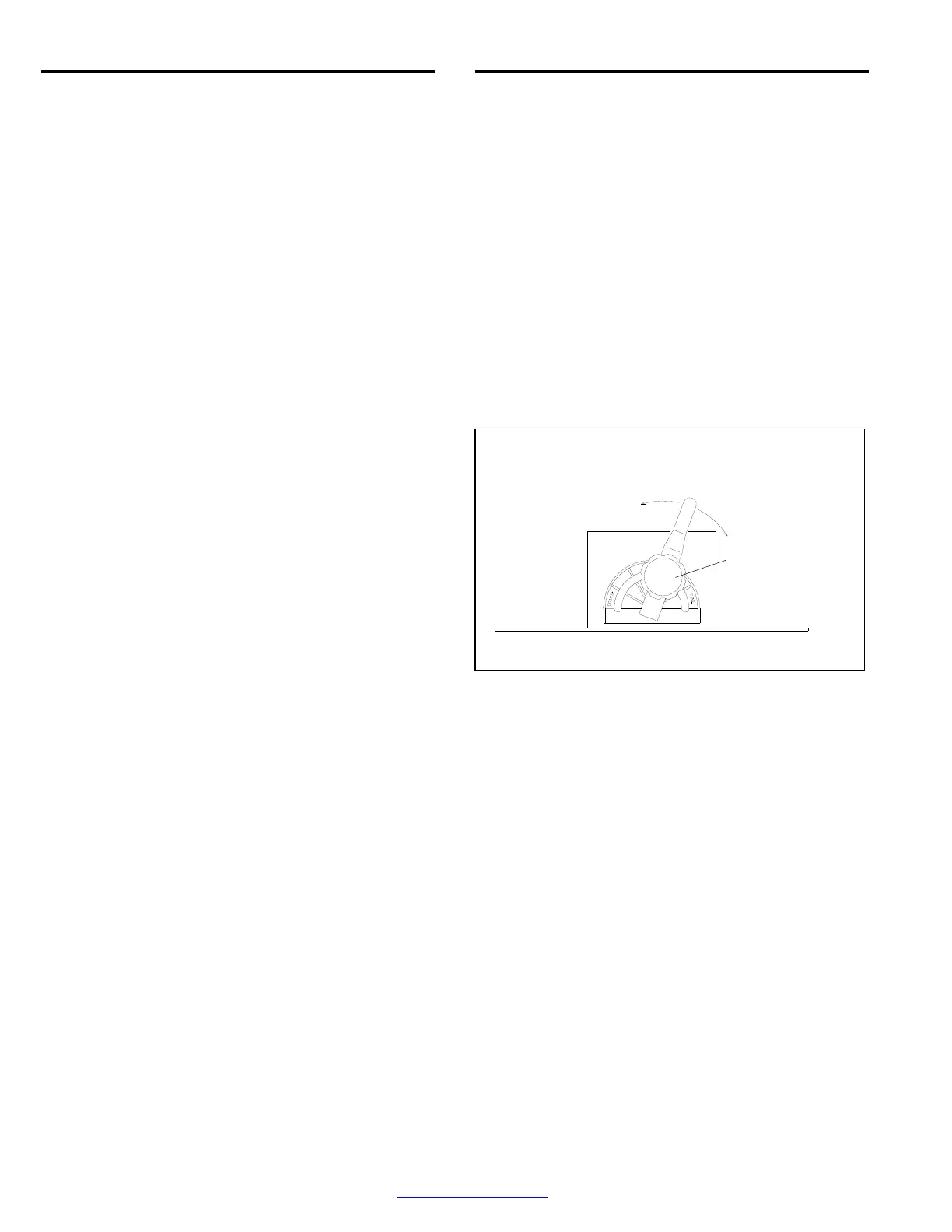
5.5.1 The vortex cylinder is located atop the reclaimer
where the flex hose connects. Adjustments are made by
loosening the handle's tensioning knob and moving the
handle to achieve the correct setting. When the correct
setting is established, tighten the locking knob to prevent
movement. Start with the lever slightly to the right (about
1 o’clock, as shown in Figure 17) of the vertical position.
5.5.2 To remove more fines: (Too much dust in
media.) Raise the cylinder by moving the lever left
toward COARSE in 1/4" increments at the indicator
plate. Allow the media to go through several blast cycles
before determining if further adjustment if needed.
5.5.3 To remove fewer fines: (Excessive usable
media is carried to the dust collector.) Lower the vortex
cylinder by moving the lever right toward FINE in 1/4"
increments at the indicator plate. NOTE: If the cylinder is
lowered too far, the reclaimer will again begin to allow
usable media to be carried over, which causes
abnormally high static pressure.
Figure 17
5.5.4 When using media finer than 180-mesh, the inlet
baffle of the reclaimer may need to be removed. Refer to
Section 1.9.6.
5.6 Cabinet Air-Inlet Damper
5.6.1 Once the inlet is initially set, per Section 2.6, it
seldom requires readjustment. The initial setting
produces approximately .5" to .75" of static pressure in
the cabinet enclosure. Do not confuse cabinet static
pressure with reclaimer static pressure, which is
controlled by the dust-collector damper, as noted in
Section 5.4. Reclaimer pressure must be set before
cabinet pressure.
5.6.2 Using a manometer (as noted in Section 5.8 and
listed in Section 9.1) is the most accurate method of
monitoring and adjusting cabinet pressure. Following the
instructions packed with the manometer, start the
exhauster, insert the needle into a glove, and adjust
pressure using the cabinet’s air-inlet damper. Open the
damper farther to decrease static pressure or close it
farther to increase pressure.
Remove more fines
from media by
moving the handle
farther to the left.
Remove fewer
fines by moving
the handle farther
to the right.
Tensioning Knob
Begin with handle at the 1 o’clock position, as shown.