BNP
®
55 SUCTION BLAST CABINET Page 8
© 2019 CLEMCO INDUSTRIES CORP. www.clemcoindustries.com Manual No. 23350, Rev G, 02/19
2.5 Connect Electrical Service
WARNING
Shorting electrical components can result in
serious injury or death from electrical shock or
equipment damage. Electrical power must be
locked out and tagged out before performing
any electrical work. All electrical work or any
work done inside a control panel or junction
box must be performed by a qualified
electrician, and comply with applicable codes.
All wiring external to the cabinet is provided by the user
to comply with local electrical codes.
2.5.1 Standard single-phase wiring
2.5.1.1 Standard 300 cfm and 600 cfm cabinets and
dust collectors are wired 120-volt single-phase. Power to
the cabinet is supplied by a U-ground plug; plug it into a
120-volt outlet.
WARNING
Do not use electrical adaptors that eliminate the
ground prong on 120-volt plugs. Doing so can
cause electric shock and equipment damage.
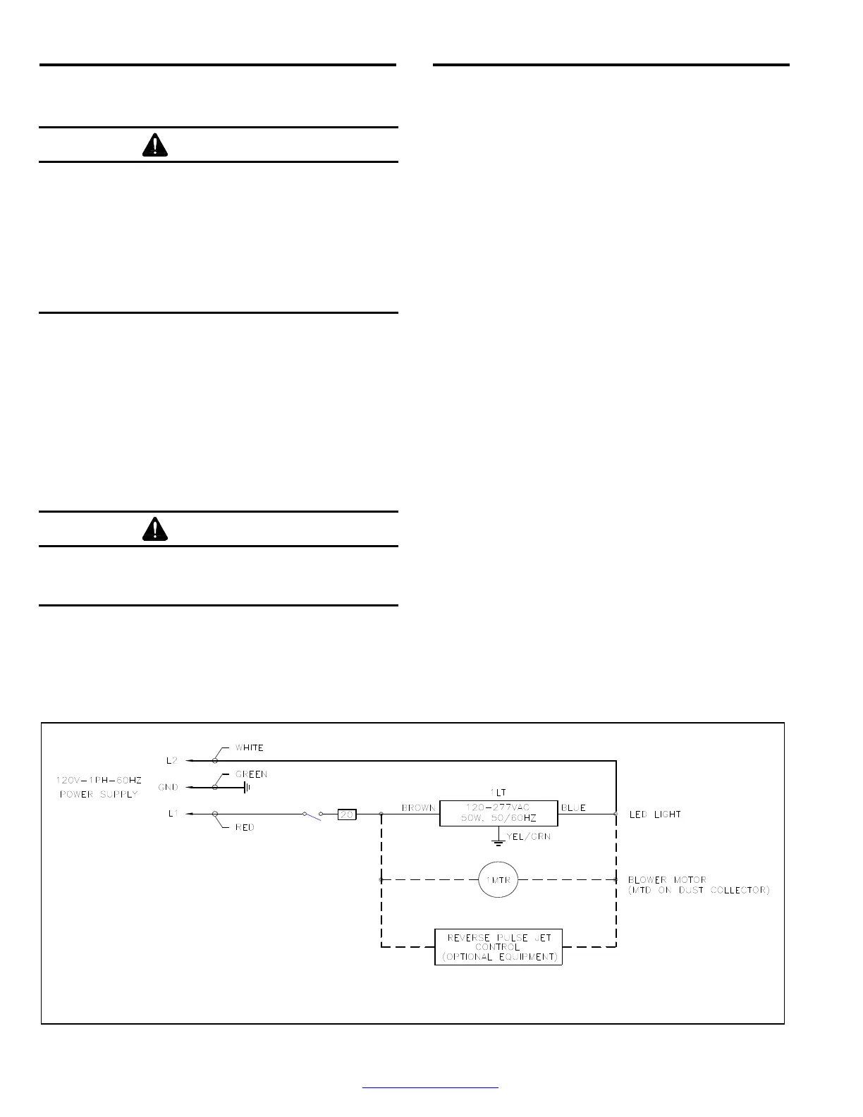
2.5.1.2 Refer to the wiring schematic in Figure 7 and
wire the dust-collector motor, per instruction on the
motor data plate, to the junction box mounted on the
cabinet.
When wired, as noted in Figure 7, the dust-collector
exhauster motor will start when the cabinet light switch
is turned ON and stop when the switch is turned OFF.
2.5.2 Optional three-phase wiring
NOTE: a wiring schematic is packed inside the cabinet’s
control panel. After wiring is completed, keep a copy of
the schematic with the manual for future reference and
for electrical replacement parts.
2.5.2.1 Refer to the wiring schematic stowed inside the
control panel mounted on the cabinet and wire from the
users disconnect to the panel and from the panel to the
dust-collector motor, per instruction on the motor data
plate.
2.5.2.2 Check the amperage on initial start up; if the
motor draws excessive amperage, gradually close the
dust-collector damper, located on the inlet on CDC-1
Dust Collectors and on the exhauster outlet on RPC-2
Dust Collectors, until the amperage is within the
specifications shown on the motor plate.
2.5.2.3 After wiring is completed, observe the warning
that follows and check the motor rotation. To check
rotation, turn the On-Off switch ON and quickly turn it
OFF, causing the motor to rotate slowly. Look through
the slots in the motor fan housing where rotation of the
fan can easily be observed. Proper rotation is indicated
by the arrow on the exhauster housing; the fan should
rotate toward the exhauster outlet. If it rotates in
reverse, change the wires, as noted on the motor plate
to reverse rotation.
Figure 7
120-VOLT, 1 PH WIRING FOR CABINET AND DUST-COLLECTOR MOTOR
Dashed lines indicate wiring by others (not
Clemco). Wiring is to be of color and gauge
shown, and marked on each end with the
wire number or terminal number as shown.