BNP
®
55 SUCTION BLAST CABINET Page 10
© 2019 CLEMCO INDUSTRIES CORP. www.clemcoindustries.com Manual No. 23350, Rev G, 02/19
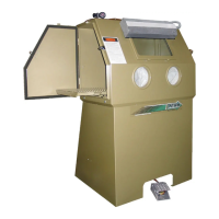
3.4 Armrest
3.4.1 Assemble the armrest and mounting brackets,
as shown in Figure 9.
3.4.2 Position the assembly so the armrest is about
even with the bottom of the arm-port opening. Mark one
hole location on the front of the cabinet at each
mounting bracket.
3.4.3 Drill a 3/8" hole at both locations and mount the
armrest using 5/16 cap screw, washers, and nuts. Install
the bolts from inside the cabinet to protect the threads
from abrasion, should the armrest need to be removed
later
Figure 9
3.4.4 Match drill the remaining four bracket holes and
install the remaining fasteners.
3.4.5 Loosen the fasteners on the slotted bracket and
raise or lower the armrest to a comfortable position.
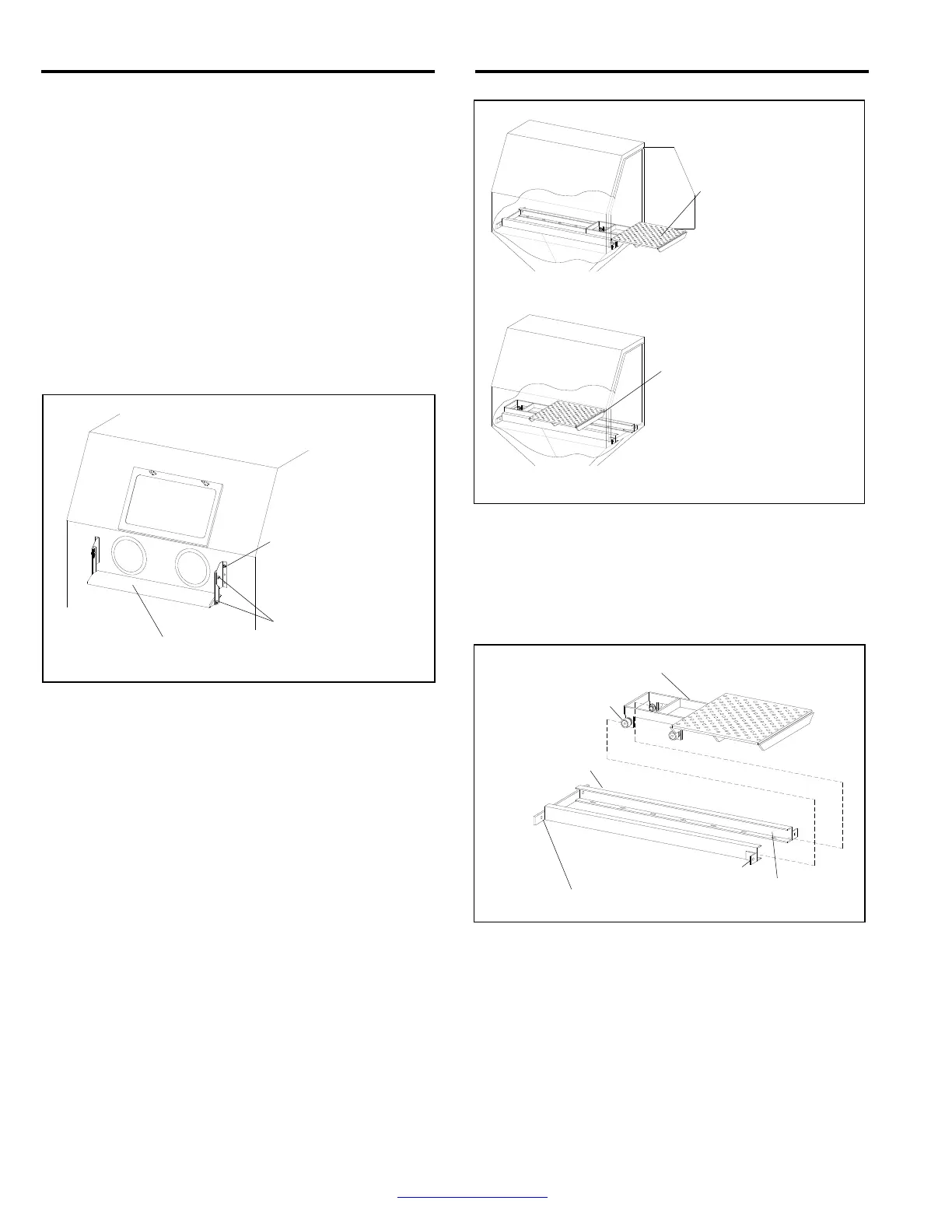
3.5 Track and Low Profile Table
Maximum Weight Capacity 500 Lbs
3.5.1 Components of track and table assembly are
shown in Figure 10. The assembly consists of:
Track assembly: mounts inside the cabinet.
Table assembly: rollers on sliding table fit inside the
track rails.
All necessary mounting fasteners.
The track may be installed on either side of the cabinet,
so the table can slide out through either the right side or
left side door. The right side is shown in the illustrations.
3.5.2 Combine the table assembly and track by sliding
the table assembly rollers into the track channels, as
shown in Figure 11.
Figure 10
NOTE: If the weight of the table and track make it too
heavy to install as an assembly, the track may be placed
inside the cabinet to predrill mounting holes, but the
table must be placed within the rails before fasteners are
installed.
Figure 11
3.5.3 Center the track and table assembly inside the
cabinet on top of the grate. Make sure the two angled
mounting brackets are facing toward the door from
which the table will slide, refer to Figure 12.
3.5.4 Match drill two 1/2" diameter holes on each side
of the cabinet, using the holes in the mounting brackets
as a template. NOTE: To prevent the track from shifting,
temporarily place a 3/8-NC x 1-1/2" bolt through each
hole after it is drilled.
Slide table to center or as
needed to position part for
blasting.
Slide table out for ease
of loading part(s). Not
to exceed 500 pounds.
Table Assembly
Track Assembly
Mounting Holes
Mounting Holes
Rollers (4)
Track Rails
5/16 x 1" x Cap Screw,
Flat Washer, Lock
Washer, and Nut
Armrest
3/8 x 1" Cap Screw
and Lock Washer