BNP
®
55 SUCTION BLAST CABINET Page 16
© 2019 CLEMCO INDUSTRIES CORP. www.clemcoindustries.com Manual No. 23350, Rev G, 02/19
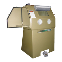
5.8.6.2 Taking readings at the reclaimer door: Open
the reclaimer fill door, remove the needle protector, and
place the needle so the tip is inside the door opening.
Carefully close the door on the needle. The side of the
needle will embed into the rubber, creating an airtight seal.
5
8
7
6
4
3
2
1
4
3
2
1
0
8
7
6
5
5
8
7
6
4
3
2
1
4
3
2
1
0
8
7
6
5
5
8
7
6
4
3
2
1
4
3
2
1
0
8
7
6
5
Figure 19
5.8.6.3 Taking frequent readings using a permanent
fitting: A permanent fitting may be installed in the
reclaimer wall, as shown in Figure 19, for taking frequent
static-pressure readings. Permanent fittings must have a
barb to accommodate the 3/16" ID tubing and have a
means of sealing the fitting when the manometer is not
in use. Use silicone sealer or other sealant to seal
around the fitting to prevent leaks. The fitting should be
capable of being capped when the manometer tube is
removed. Sealing the fitting will prevent leaks that alter
the reclaimer’s separation efficiency. Air drawn into the
reclaimer will cause carry over of good media to the dust
collector.
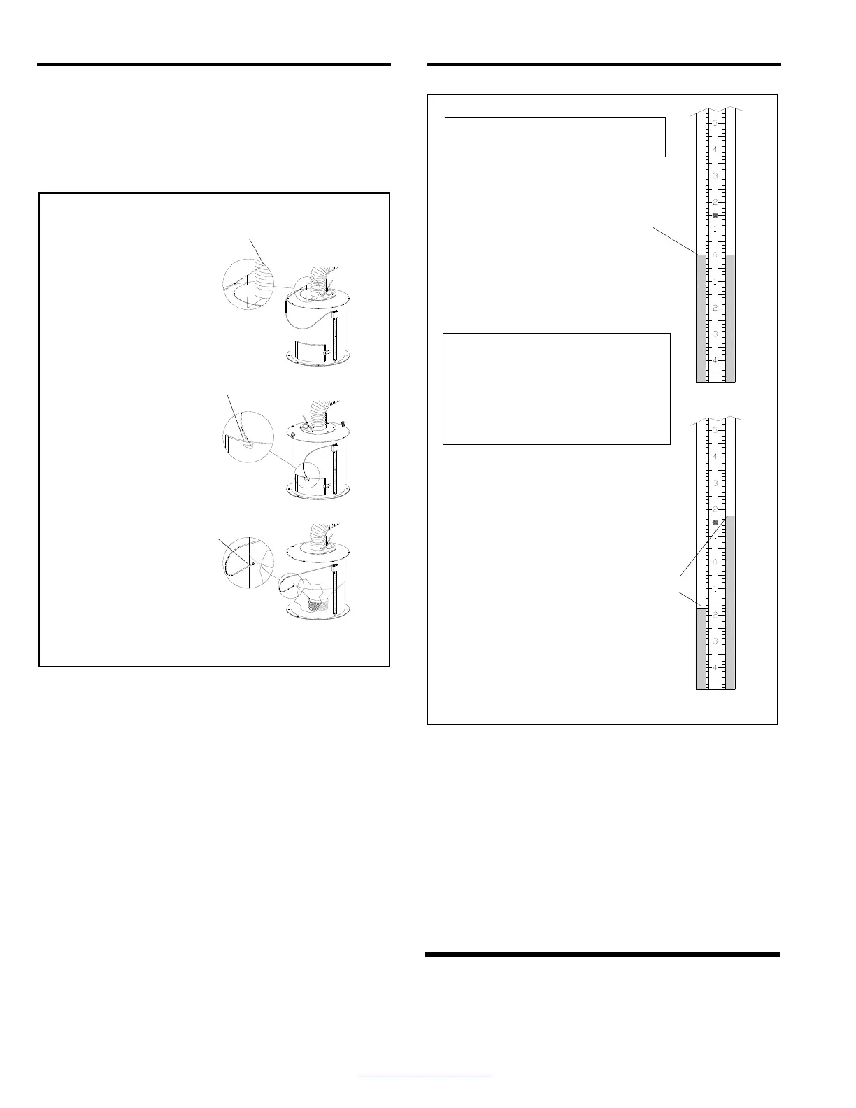
5.8.7 Adjust the slide rule to align the zero with the
fluid level. Refer to the upper part of Figure 20.
5.8.8 Open cabinet doors and turn the exhauster ON.
The negative (static) pressure will move fluid in the tube.
NOTE: Readings must be taken with the cabinet
doors open and with the exhauster running.
Figure 20
5.8.9 To find the static pressure, add the number of
inches the fluid travels up one column to the inches the
fluid travels down the other column. Refer to the
example in Figure 20.
5.8.10 After taking the readings, replace the needle
protector. Close the manometer valves and store the
manometer in the original container in a clean area.
NOTE: If the manometer installation is permanent, the
manometer may remain on the reclaimer body after the
valves are closed.
The manometer must be vertical when
taking pressure readings.
8"
Some items removed or rotated for clarity.
To obtain the pressure reading: With
the exhauster ON, add the number of
inches the fluid travels up the column
to the inches the fluid travels down
the other column. The total is the
static-pressure reading.
With the exhauster OFF,
slide the rule to align the
zero with the fluid level.
Refer to Paragraph 5.8.6.3
for taking frequent readings.
Install a permanent fitting in
the reclaimer wall just below
the inner cone as shown.
Refer to Paragraph 5.8.6.2
for taking readings at the
reclaimer door. Place the
needle so the tip is inside
the door opening. Carefully
close the door on the needle.
Refer to Paragraph 5.8.6.1 for
taking readings in the flex hose.
Insert the needle into flex hose 8"
above the top of the reclaimer.
In the example shown, fluid traveled up
the right column 1-3/4"
and down the left column 1-3/4".
Static pressure is determined by adding
the reading together. In the example, the
static pressure is 3-1/2".