EasyManua.ls Logo

CLIMAVENETA CHD U-2T 706 User Manual

CLIMAVENETA CHD U-2T 706
38 pages
To Next Page IconTo Next Page
Page #1 background imageLoading...
Page #1 background image
OPERATING AND INSTALLATION MANUAL
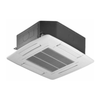
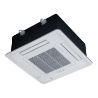
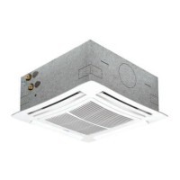
I - VENTILCONVETTORE CASSETTE
GB - FAN COIL CASSETTE
FR - VENTILO-CONVECTEURS CASSETTE
DE - KASSETTEN-KLIMAKONVEKTOREN
ES -
VENTILADORES CONVECTORES CASSETTE
I) Vi preghiamo di leggere con attenzione
il presente manuale prima di mettere in
funzione l’apparecchio.
GB) Please read this guide carefully before
switching on the appliance.
FR) Nous vous prions de bien vouloir lire
attentivement ce mode d'emploi avant
de mettre l'appareil en fonction.
DE) Bitte lesen Sie vor der Inbetriebnahme
des Geräts aufmerksam diese
Bedienungsanleitung.
ES) Les rogamos lean con atención el
presente manual antes de encender el
aparato.
MODELLI
MODELS
MODÈLES
MODELLE
MODELOS
CHD U-2T 506-1209
CHD U-4T 506-1209

Questions and Answers:

CLIMAVENETA CHD U-2T 706 Specifications

General IconGeneral
BrandCLIMAVENETA
ModelCHD U-2T 706
CategoryAir Conditioner
LanguageEnglish

Summary

Operating and Installation Manual Overview

General Safety Warnings and Precautions

Operational Safety Procedures

Guidelines for safe operation, ventilation, and storm conditions.

Maintenance and Personnel Requirements

Qualified personnel, manual preservation, and modification approval requirements.

Installation and Electrical Safety

Personnel training, electrical work supervision, and regulatory compliance.

Essential Safety Rules

General Electrical Product Safety

Fundamental safety rules for operating electrical products.

Electrical and Cable Handling Safety

Precautions for touching, cleaning, and handling electrical cables.

Installation and Handling Safety

Safety measures during installation, including lifting and carrying.

Operational and Maintenance Safety

Safety rules for unit operation and maintenance procedures.

Technical Data: U-2T Models

Technical Data: U-4T Models

Air Flow and Cooling Performance

Tables detailing air flow rates and cooling capacities for U-4T models.

Heating Performance Data

Tables detailing heating capacities for U-4T models.

Indoor Unit Installation Guidelines

Water Piping Diagrams

Typical Water Piping Layout

Schematic of a standard water piping setup for the fan coil.

Water Connection Details and Precautions

Electrical Connection Principles

General Connection Instructions

Guidelines for performing electrical connections safely and according to regulations.

Unit Earthing and Wiring Standards

Requirement for earthing the unit and wire cross-section standards.

Hydronic Wiring Diagrams (No Control)

Wiring Diagram: CHD 506-706

Wiring diagram for hydronic cassette without control for CHD 506-706.

Wiring Diagram: CHD 809-1209

Wiring diagram for hydronic cassette without control for CHD 809-1209.

Single Connections with NSW Control

Wiring Diagram: CHD 506-706 + NSW

Wiring diagram for CHD 506-706 connected to NSW wall-mounted control.

Wiring Diagram: CHD 809-1209 + NSW

Wiring diagram for CHD 809-1209 connected to NSW wall-mounted control.

Single Connections with ATW-MTW-PSW Control

Wiring Diagram: CHD 506-706 + ATW-MTW-PSW

Wiring diagram for CHD 506-706 with ATW-MTW-PSW controls.

Wiring Diagram: CHD 809-1209 + ATW-MTW-PSW

Wiring diagram for CHD 809-1209 with ATW-MTW-PSW controls.

Multiple Connections with SPB + NSW Control

Wiring Diagram: CHD 506-706 + SPB + NSW

Wiring diagram for CHD 506-706 with SPB and NSW controls for multiple units.

Multiple Connections with SPB + NSW Control (Cont.)

Wiring Diagram: CHD 809-1209 + SPB + NSW

Wiring diagram for CHD 809-1209 with SPB and NSW controls for multiple units.

Multiple Connections with SPB + ATW/MTW/PSW Control

Wiring Diagram: CHD 506-706 + SPB + ATW/MTW/PSW

Wiring diagram for CHD 506-706 with SPB and ATW/MTW/PSW controls.

Multiple Connections with SPB + ATW/MTW/PSW Control (Cont.)

Wiring Diagram: CHD 809-1209 + SPB + ATW/MTW/PSW

Wiring diagram for CHD 809-1209 with SPB and ATW/MTW/PSW controls.

NSW Wall-Mounted Control Overview

NSW Control Functionality Description

Regulates air, temperature, and mode; switches fan coil on/off.

NSW Control: Functions and Configuration

NSW Control Digital Outputs Configuration

Details on valve control (YV1, YV2) for different system types.

PSW Wall-Mounted Control Overview

PSW Control Functionality Description

Regulates airflow, temperature, and mode; switches fan coil on/off.

PSW Control: Functions and Configuration

PSW Control Digital Outputs Configuration

Details on valve control (YV1, YV2) for different system types.

MTW Wall-Mounted Control Overview

MTW Control Functionality Description

Regulates air, temperature, and mode; switches fan coil on/off.

MTW Control: Functions and Configuration

MTW Control Digital Output Configuration

Details on valve control (YV1, YV2) for different system types.

ATW Wall-Mounted Control Overview

ATW Control: Functions and Configuration

Routine Maintenance Procedures

Cleaning the Air Filters

Step-by-step guide for cleaning and reinstalling air filters.

Maintenance Safety and Spare Parts

General Maintenance Safety Rules

General safety and procedural rules for maintenance work.

Important Maintenance Reminders

Crucial reminders before cleaning/maintenance and filter replacement.

Operational Precautions

Troubleshooting Common Issues

Motor Rotation Problems

Checks for power, wiring, switches, and commutator for motor issues.

Heating/Cooling Performance Issues

Checks for filter cleanliness, hydraulic circuit air, and venting.

Water Leakage Troubleshooting

Checks for unit slope, condensate drain, and clogs.

Malfunctions and Corrective Actions

Fan Operation Malfunctions

Troubleshooting for fan not running or low airflow issues.

Water Leakage and Condensation Issues

Troubleshooting for water leaks, condensation on air registers.

Related product manuals