Do you have a question about the CLIMAVENETA i-CXW Series and is the answer not in the manual?
| Brand | CLIMAVENETA |
|---|---|
| Model | i-CXW Series |
| Category | Air Conditioner |
| Language | English |
Guidelines for manual usage and reference.
Information on how to identify the unit via its rating label.
Details on the fan motor assembly for a-CXW models.
Details on heat exchanger coils for i-CXW models.
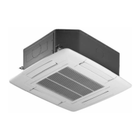
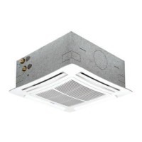
Details on the metal intake grill, Coanda effect, and dimensions.
Information on the HB/i-HB power boards for unit control.
Details on mixing primary air with recirculated air.
Features and functions of the MTW thermostat.
Features and functions of the ATW thermostat.
Features and functions of the EKW thermostat.
Features of the iKW programmable thermostat with LCD.
Illustrates air throw distances based on speed and size.
Electrical data and performance specs for a-CXW 2-pipe.
Electrical data and performance specs for a-CXW 4-pipe.
Electrical data and performance specs for i-CXW 2-pipe.
Electrical data and performance specs for i-CXW 4-pipe.
Dimensions and weights of the appliance.
Covers manual scope and required qualifications for work.
Warnings and advice for unit installation.
Safety guidelines for maintenance and repairs.
Guidelines for safe appliance usage.
Fundamental operating data for fan coil and heat exchanger.
Dimensional drawings for specific a-CXW and i-CXW models.
Dimensions for 2-pipe and 4-pipe valves.
Dimensions for 2-pipe valves for larger models.
Steps and requirements before starting installation.
Guidelines for selecting the installation location.
Recommended environmental conditions for operation.
Instructions on how to fix the fan coil unit.
Steps for connecting primary air ducts.
Information on fan coil air supply outlets and flow rates.
Maximum allowable values for water quality in the circuit.
Information on heat transfer fluid properties and limits.
Description of the condensate drain pan function.
Information on valve connections and positions.
Details on supplied two- or three-way valves.
Details on simplified valve kits.
Pressure drop graphs and coefficients for a-CXW 4-pipe.
Pressure drop graphs and coefficients for a-CXW 2-pipe.
Cold water coil pressure drop graphs and coefficients.
Instructions for connecting wires from the remote control.
Details on the unit's electrical components and their functions.
Information about the electric coil and its safety features.
Details on safety thermostats for electric coils.
Instructions for installing valves supplied by the installer.
Connection diagram for a-CXW units with MTW controller.
Wiring diagram for single actuator connections.
Wiring diagram for double actuator connections.
Connection diagram for a-CXW units with ATW controller.
Wiring diagram for ATW single actuator.
Connection diagram for a-CXW units with ATW controller and electric heater.
Wiring diagram for electric heater with single actuator.
Wiring diagram for a-CXW units with EKW/IKW controllers.
Wiring diagram for electronics with single actuator.
Wiring diagram for a-CXW units with EKW/IKW controllers and electric heater.
Wiring diagram for electric heater with single actuator.
Wiring diagram for i-CXW units with ATW-EC controller.
Wiring diagram for ATW-EC with single actuator.
Wiring diagram for i-CXW units with ATW-EC controller and electric heater.
Wiring diagram for electric heater with single actuator.
Wiring diagram for i-CXW units with EKW/IKW controllers.
Wiring diagram for electronics with single actuator.
Wiring diagram for i-CXW units with EKW/IKW controllers and electric heater.
Wiring diagram for electric heater with single actuator.
Details and functions of the HB/i-HB power board kit.
Diagram of fan coil wiring with controllers and expansion kits.
Details on the RS485 interface kit for BMS integration.
Information on the 0-10 Vdc valve expansion kit.
Instructions for electrical connections to HB/i-HB board.
Explanation of dipswitch settings for HB/i-HB boards.
Technical specifications and connection procedures for the RS485 kit.
Details on integrating local Master-Slave networks into BMS.
General notes on installation and maintenance.
Essential safety requirements for installation and use.
Air quality requirements for installation environments.
Instructions for cleaning the unit's filter.
Procedures for cleaning the fan, motor, and checking capacitor.
Periodic maintenance schedule and tasks.
Troubleshooting guide for common faults and their solutions.
Disposal instructions for packaging, filters, and electronics.
Procedures for dismantling and disposing of the unit.
Instructions for cleaning and replacing the filter.
Faults and their solutions.
General maintenance procedures.
Troubleshooting steps for fan non-operation.
Troubleshooting steps for low air flow.