Do you have a question about the CLIMAVENETA i-KIR MTD and is the answer not in the manual?
Manufacturer disclaims liability for document use and unauthorized modifications.
Rules for safe operation and installation of electrical and water systems.
Check delivered goods against delivery note and packaging label for damage.
Guidelines for lifting and moving units safely using appropriate equipment.
Instructions for storing units to prevent damage from environmental factors.
Procedures for safely removing packaging and checking contents.
Guidelines for moving units after packaging removal.
Describes product identification data on the packaging.
Details unit specifications, serial number, and required service information.
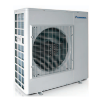
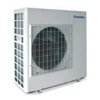
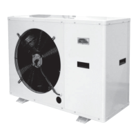
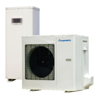
Details available heat pump versions (heating only, reverse-cycle) and their features.
Criteria for selecting the appropriate location for unit installation.
Guidelines for physically placing the unit, considering weight and access.
Essential components that must be installed in the water circuit.
Optional components for improved water circuit performance and safety.
Instructions for installing temperature probes in water connections.
Precautions and methods to prevent freezing in the water circuit.
Information on using antifreeze and its effect on performance.
Recommended water quality parameters for system operation.
How fouling affects performance data and correction factors.
Steps for connecting the system pipes to the heat pump.
Information on system water content and expansion vessel sizing.
Guidance on calibrating the safety valve.
How to correctly install and manage the condensate drain.
Procedure for filling the water circuit and checking pressure.
Procedure for draining the water circuit, considering antifreeze.
Detailed instructions for wiring connections to terminal blocks.
Table detailing required wire sizes for power and connection cables.
Table providing electrical specifications and fuse ratings for different models.
Diagram showing the layout of the inside module's electrical panel.
How to connect power when the inside module is powered via the heat pump.
Wiring instructions when heat pump and inside module are powered independently.
How to connect the outside air temperature probe to the inside module.
How to connect water temperature probes to the heat pump and inside module.
Instructions for installing and connecting the A5 room controller.
Wiring and configuration of the 3-way valve for DHW production.
Describes optional connections, like KM2 System outlet electric heater.
How to control the outlet electric heater in replacement or supplementary modes.
Configuration parameters for the electric heater in replacement mode.
Configuration parameters for the electric heater in supplementary mode.
Enabling supplementary electric heater at all times.
Configuration parameters for supplementary electric heater operation.
Using a boiler as a supplementary or replacement heat source.
How to control the boiler for replacement or supplementary heating.
Configuration parameters for boiler operation in replacement mode.
Configuration parameters for boiler in supplementary mode.
Enabling supplementary boiler heating for all outdoor air temperatures.
Configuration parameters for supplementary boiler operation.
Managing an electric heater for DHW storage.
Activating electric heater to reach DHW temperatures.
Function to eliminate Legionella bacteria using electric heater.
Configuring HL1 contact for alarm, pump, or dehumidifier.
Configuring HL1 for visual/audible alarm signals.
Configuring HL1 to activate a secondary circuit pump.
Configuring HL1 to activate a dehumidifier.
Switching the unit on/off remotely using a control unit.
Managing cooling/heating mode via a remote control unit.
Selecting heat pump operation priority using a remote contact.
Using SA5 contact to stop operation due to excess power consumption.
Activating tank refilling based on electricity rates.
Connecting the system flow switch, a compulsory component.
Measuring domestic hot water temperature using probe BT8.
Physical dimensions and weight of the outdoor units.
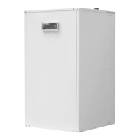
Physical dimensions and weight of the inside modules.
Operating limits graph for cooling mode based on temperatures.
Operating limits graph for heating mode based on temperatures.
Pump performance curves showing head vs flow rate for different models.
Pre-start checks for installation, safety, and connections.
Steps to ensure the unit is ready for its initial start-up.
Procedure for the initial power-up and start of the unit.
Procedure to activate the unit and zone valve via the controller.
How to choose the operating mode (heating, cooling, auto) on the room controller.
How to adjust the desired room temperature using the controller.
Identification and function of buttons on the room controller.
Explanation of symbols and information displayed on the room controller.
Explains the meaning of symbols used on the room controller.
How to view extra information like temperatures and humidity by pressing the knob.
Step-by-step guide to setting the correct time and date on the controller.
Procedure to activate the unit and zone valve via the controller.
How to choose heating, cooling, or automatic mode.
How to adjust the desired room temperature.
How to enable or disable domestic hot water (DHW) production.
How to set the desired DHW temperature.
How to customize on/off times for zones using time bands.
Procedure to activate programmed time bands.
Procedure to deactivate programmed time bands.
How to turn off the unit and zone valve using the controller.
How to access different user and installer programming levels.
Factors influencing water outlet temperature calculation.
How outside temperature affects water outlet set point via compensation curves.
How room temperature affects heating water outlet temperature.
Minimum and maximum water outlet temperatures allowed in heating.
How outside temperature affects water outlet set point in cooling mode.
How room humidity affects water outlet temperature set point.
How the unit automatically switches between heating and cooling.
How the system pump operates to save energy.
Disabling compensation curves for fixed set point operation.
How frost protection works based on water temperature.
How frost protection works based on outside air temperature.
Table listing system configurations and required expansion modules.
Diagram showing the water circuit for configuration 0.
Diagram showing the water circuit for System Number 0, Configuration '1'.
Diagram illustrating the electrical wiring for System Number 0.
Indication when an alarm is active on the unit.
How to view active alarm codes on the controller.
Procedure to reset alarms after resolving the issue.
How to access the log of recently activated alarms.
List of alarm codes, causes, and solutions for remote keypad display.
Alarms displayed on the PCB display in the compressor compartment.
How to view data from probes on the outdoor unit display.
How to reset alarms displayed on the unit's board.
How to view the alarm log directly on the unit's board.
Activating emergency heating via electric heaters if the heat pump fails.
Activating emergency DHW heating via the storage tank electric heater.
Procedures for safely shutting down the unit for extended periods.
Procedures for maintenance tasks not on a fixed schedule.
Recommendation for chemical flushing of the heat exchanger.
Procedures for handling refrigerant gas leaks and recharging.
Checkboxes to mark included system types (heating, cooling, DHW).
Diagram and fields for describing the heating system circuit components.
Diagram and fields for describing the DHW circuit components.
Checklist for required components in the water circuit.
Checklist for verifying installation and startup procedures.
| Brand | CLIMAVENETA |
|---|---|
| Model | i-KIR MTD |
| Category | Heat Pump |
| Language | English |