EasyManua.ls Logo

CLIMAVENETA i-KIR2 MTD User Manual

CLIMAVENETA i-KIR2 MTD
68 pages
To Next Page IconTo Next Page
Page #1 background imageLoading...
Page #1 background image
INSTALLATION - USER - MAINTENANCE MANUAL
i-KIR2 MTD reverse-cycle air/water heat
pump with DC inverter-driven
compressors, domestic hot water
production, axial-flow fans and
hydronic unit for outdoor installation
EN
i-KIR2 MTD
0011m ÷ 0061m
Question and Answer IconNeed help?

Do you have a question about the CLIMAVENETA i-KIR2 MTD and is the answer not in the manual?

CLIMAVENETA i-KIR2 MTD Specifications

General IconGeneral
BrandCLIMAVENETA
Modeli-KIR2 MTD
CategoryHeat Pump
LanguageEnglish

Summary

General Warnings

Waiver of Liability

Manufacturer disclaims liability for improper use or incorrect installation.

Fundamental Safety Rules

Essential safety guidelines for installation and operation.

Receiving and Handling Product

Visual Inspection

Steps for checking delivered goods against documentation and for intactness.

Storing the Units

Guidelines for proper storage to prevent damage and safety hazards.

Handling Packaged Units

Methods for lifting and moving units safely using equipment.

Removing the Packaging

Instructions for safely removing packaging and handling components.

Unit Identification

Rating Plate

Information on the unit's technical specifications and serial number for service.

Nomenclature

Breakdown of model designation and power supply details.

Description of Standard Unit

Versions Available

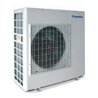
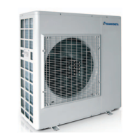
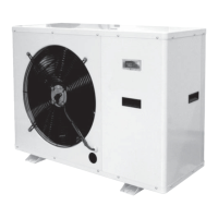
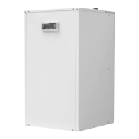
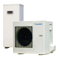
Details on different unit versions and their capabilities.

Dimensional Drawings

Minimum Clearances

Heat Pump Installation

Choice of Installation Site

Criteria for selecting an appropriate installation location for the unit.

Positioning

Instructions for physically placing and securing the unit for optimal operation.

Water Connections

Water Connection Dimensions

Specific dimensions for water inlet and outlet connections for each model.

Required Components

Essential components that must be installed in the water circuit for safety and function.

Recommended Components

Optional components that enhance the water circuit's performance and safety.

Risk of Freezing

Ethylene Glycol Solutions

Water Quality

System Circuit Connection

Utility Water Circuit Connection Diagram

Condensate Drain

Filling the System

Emptying the System

Electrical Connections

How to Connect Cables to Terminal

Detailed instructions and precautions for wiring the unit's terminals.

Electrical Data at Maximum Conditions

Wiring Diagrams

Remote Contact Terminal Board

Table of Analogue and Digital Inputs/Outputs

Detailed list of terminal functions and their analogue/digital signal types.

Mains Power Supply Connections

Installer Connections

Outside Air Temperature Probe Connection

Instructions for installing and enabling the remote outside air temperature probe.

Remote Controller Connection

Installation guidelines for the remote controller for room temperature control.

Installation Procedure

3-Way Valve for Domestic Hot Water Production

DHW Storage Electric Heater (DHW T.Probe)

Water Storage Tank Temperature Probe (Buffer T. probe)

Low Temperature System Management (Zone 1)

Zone 1 Dehumidifier Management

High Temperature System Management (Zone 2)

Configurable Contact (ON/OFF or EHS Alarm)

Boiler Backup Contact (EHS Alarm)

DHW Remote Contact

Remote Cooling/Heating Mode Contact (Heating/Cooling Mode)

Remote Low Tariff Contact (Low Tariff)

Remote Night Mode Contact (Night Mode)

Heating/Cooling Mode Output

Configurable Contact (Alarm/Ambient T. Reached)

Alarm Signal Contact

Room Set Point Reached Contact

Dual Set Point Contact (Dual Set Point)

Parameters for Setting Second Water Temperature Set Point (Fixed Set Point)

Parameters for setting fixed temperature set points for zone 2.

Parameters for Setting Compensation Curve (Heating/Cooling)

Parameters for setting compensation curves for zone 2 temperature control.

Optional Connection

System Outlet Electric Heater (Backup Heater)

Outlet Electric Heater Control

Supplementary Heating Always Enabled

Auxiliary Heat Source (EHS)

Boiler Control

Supplementary Heating Always Enabled

DHW Storage Electric Heater Contact

DHW Storage Electric Heater Control

Legionella Prevention Function with Electric Heater

System Flow Switch (Flow Switch)

General Technical Data

Operating Limits

Pump Characteristics

Checking and Starting Up the Unit

Checks Before Starting the Unit

Pre-startup checklist for ensuring proper installation and safety.

Preparing for First Start Up

Steps to take before the initial startup, including installation verification.

Starting Up for the First Time

Procedures for safely performing the initial startup of the heat pump.

Remote Controller

Description or Room Controller Buttons and Display

Display

Operation and Functions of the Room Controller

Meaning of the Symbols

Explanation of symbols used on the room controller.

Setting the Time and Date

Step-by-step guide for setting the current time and date.

Switching ON

Procedure for turning the unit ON using the remote controller.

Selecting the Operating Mode

Selecting the Room Set Point

Domestic Hot Water Production

Modifica Set-point Acqua Calda Sanitaria

Programming the Time Bands

Set the COMFORT and ECONOMY Set Point

Time Band 2 End COMFORT Set Point

Enabling/Disabling the Time Bands

Programming the DHW, Low Tariff and Night Mode Time Bands

Time Band 2 End DHW COMFORT Set Point

Enabling/Disabling the DHW, Low Tariff, Night Mode Time Bands

Lock Keypad

Procedure for Accessing and Setting Parameters

User-Level Access

Installer-Level Access

Service-Level Access

Control and Operating Characteristics

A) Compensation Curve

Setting compensation curves for optimized operation based on system type.

List of Parameters for Setting Compensation Curve

Parameters for configuring compensation curves for various zones and modes.

B) Heat Pump Operation with Fixed Set Point

List of Heat Pump Operating Parameters with Fixed Set Point

Relative Humidity Control in Radiant Heating/Cooling Systems

Water Outlet Temperature Compensation

Unit Circulator Pump Operating Modes

Unit Circulator Pump Curve Selection

Pump Anti-blocking Function

Frost Protection

Maintenance and Service

Alarm Signals

How alarm conditions are indicated on the unit and controller.

Reset Alarms

Steps to reset active alarms on the unit.

Alarm Log

How to view and delete the log of past alarms.

Table Alarms

Error Code Details (Page 59)

Error Code Details (Page 60)

Display Heat Pump Operating Variables on Remote Controller

Display Heat Pump Operating Variables on Display

Scheduled Maintenance

Unscheduled Maintenance

Chemical Washing

Refrigerant Gas Charge

Disposal

Useful Information

Installer Operations Checklist

Systems Included

Options for marking installed system types and components.

Heating System Circuit

Diagram and fields for describing the heating system circuit components.

Domestic Hot Water Circuit

Diagram and fields for describing domestic hot water circuit components.

Have the Following Checks Been Completed?

Checks (as described in the paragraph on "Checking and starting up the unit")

Related product manuals