EasyManua.ls Logo

CLIMAVENETA LIFE2 AT MODBUS CONTROL KIT User Manual

CLIMAVENETA LIFE2 AT MODBUS CONTROL KIT
6 pages
To Next Page IconTo Next Page
Page #1 background imageLoading...
Page #1 background image
Questo foglio istruzioni è parte integrante del libretto dell’apparec-
chio sul quale è stato installato l’accessorio. A tale documento si
rimanda per le AVVERTENZE GENERALI.
Comando a bordo fan-coil AT
Il comando AT consente la regolazione dell’aria (3 velocità + auto), la
regolazione della temperatura tramite termostato elettronico, la selezio-
ne dello stato di funzionamento estate/inverno/auto e l’accensione/spe-
gnimento del fan-coil.
These instructions are an integral part of the booklet accompanying
the appliance on which the accessory is installed. Refer to this book-
let for the GENERAL RECOMMENDATIONS.
D
ESCRIZIONE DESCRIPTION
On board controls AT
The AT control is used to regulate the air (3 speeds + auto), the temper-
ature through electronic thermostat, to select the summer/winter/auto
mode of operation and to switch the fan-coil on/off.
CONTENUTO DELLA CONFEZIONE - CONTENTS OF THE KIT
Descrizione - Description Q.tà / Qty.
Comando elettronico AT completo di sonde - AT electronic control with probes
1
Staffa di fissaggio - Fastening bracket 1
Viti di fissaggio - Fastening screws 3
Foglio istruzioni - Instruction sheet 1
KIT COMANDO AT - MODBUS
AT MODBUS CONTROL KIT
DATI TECNICI - TECHNICAL DATA
Dati tecnici Technical data
Tensione di alimentazione Supply voltage 230 V ~ ±10%
Frequenza di alimentazione Supply frequency 50/60 Hz
Portata contatti Contact rating 1A (cosØ ≥0.85; 230V)
Sonda aria remota Remote air probe NTC 10 kOhm @ T = 25 °C
Sonda acqua remota Remote water probe NTC 10 kOhm @ T = 25 °C
Campo di regolazione termostato Regulation range +14°C a 30°C
Temperatura di stoccaggio Storage temperature -20 °C / +85 °C
Umidità massima di stoccaggio Max. storage humidity
90% (non condensante)
(not condensing)
Temperatura di esercizio Working temperature 0 °C / +55 °C
Umidità massima di esercizio Max. working humidity
90% (non condensante)
(not condensing)
Grado di protezione Index of protection IP 30
Materiale contenitore Case material
PC+ABS (autoestinguente V0)
(flame retardant V0)
Colore Color RAL 9003 (bianco) (white)
Dimensioni Dimensions 120 x 75 x 25 mm
Peso Weight 0,150 kg
Manopola della temperatura
Temperature selector
La scelta della temperatura ambiente è possibile rego-
lando la posizione della manopola alla temperatura
desiderata tra +14°C a +30°C.
Adjust the temperature as required by turning the tem-
perature selector from +14°C to 30°C.
Pulsante delle funzioni
Function button
La scelta del modo di funzionamento è possibile trami-
te il pulsante .
Select the mode of operation pushing the button.
Led modalità di funzionamento
Mode led
Raffreddamento - Cooling
Riscaldamento - Heating
Spegnimento - Off
Modalità funzionamento automatica
Automatic setting
Pulsante della ventilazione
Speed button
La scelta della velocità del ventilatore è possibile tra-
mite il pulsante .
La pressione ripetuta del pulsante determina la velo-
cità richiesta.
Select the fan speed pushing the button.
The repeated pressure of fan button determines speed
required.
Velocità di ventilazione massima
Maximum fan speed
Velocità di ventilazione media
Medium fan speed
Velocità di ventilazione minima
Minimum fan speed
Velocità automatica di ventilazione
Automatic fan speed
Led di segnalazione
LED
Led blu acceso: attivazione riscalda-
mento-condizionamento
Led blu lampeggiante: funzione Hot start
/ Too cool attiva
Blue LED: Heating / Cooling plus regu-
lator call
Blue LED blinking: Hot start / Too Cool
function active
Led blu acceso: richiesta modo
di funzionamento Raffreddamento
Blue LED: operation in Cooling mode
Led blu acceso: richiesta modo
di funzionamento Riscaldamento
Blue LED: operation in Heating mode
Led blu acceso: selezione
automatica della modalità
raffreddamento / riscaldamento
Blue LED: automatic cooling / heating
mode selection
Question and Answer IconNeed help?

Do you have a question about the CLIMAVENETA LIFE2 AT MODBUS CONTROL KIT and is the answer not in the manual?

CLIMAVENETA LIFE2 AT MODBUS CONTROL KIT Specifications

General IconGeneral
BrandCLIMAVENETA
ModelLIFE2 AT MODBUS CONTROL KIT
CategoryThermostat
LanguageEnglish

Summary

Description of Controls

On board controls AT

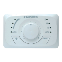
Regulates air speed, temperature, operating mode, and fan-coil on/off.

Temperature selector

Allows setting ambient temperature between +14°C and +30°C.

Function button

Selects operating mode by pressing the MODE button.

Mode led

Indicates cooling, heating, off, or automatic modes via LED.

Speed button

Selects fan speed by repeatedly pressing the button.

LED indicators

Blue LED signals heating/cooling, hot start, or too cool functions.

Contents of the Kit

Kit Components

Lists AT electronic control, fastening bracket, screws, and instruction sheet.

Technical Data

Technical Specifications

Details supply voltage, frequency, contact rating, probes, temperature ranges, and dimensions.

Description of Functions

SUMMER mode of operation

Manages summer mode valves and fans based on thermostat calls and set points.

WINTER mode of operation

Manages winter mode valves and fans based on thermostat calls and set points.

AUTO mode of operation

Automatically selects mode based on 2-pipe or 4-pipe system type.

Automatic fan speed

Adjusts fan speed based on the difference between desired and current room temperature.

Hot Start function

Activates fan only if water is sufficiently hot (T≥32 °C) in heating mode.

Too Cool function

Activates fan only if water is cold enough (T≤18 °C) in cooling mode.

Periodic fan operation

Promotes air destratification for accurate room temperature sensing.

Connection and Installation

Connection to Building Management System

Details connecting the AT Modbus control unit to a BMS via TTL port and Modbus RTU.

Installation requirements

States that installation must be done by qualified personnel after cutting power.

Wiring and Sensor Installation

Connect wiring to fan coil terminal block

Connect the wiring to the fan coil terminal block following the electrical diagram.

Water temperature sensor installation

Insert sensor through hole, place bulb on inlet pipe for accurate temperature measurement.

Air temperature sensor installation

Fit the air temperature sensor bulb into the provided clip.

Electrical Connections and Configuration

Electrical Connections

Diagram and legend for connecting wires to the AT control unit terminals.

Analog Inputs Configuration

Details configuration for remote air and water sensor inputs.

Digital Outputs Configuration

Explains control of main and secondary valves (YV1, YV2) for 2-pipe/4-pipe systems.

Dip Switch Configuration and Features

Dip Switch Settings

Guides installer on setting system type (2-pipe/4-pipe) using 5 dip switches.

Failure Display

Explains LED indications for inhibited ventilation and temperature sensor failures.

Digital Inputs Configuration

Configures digital inputs for window contact, economy mode, or remote changeover.

Parameter Configuration and First Use

Parameter Configuration Procedure

Step-by-step guide to configure parameters using MODE and FAN buttons.

First Time of Use

Instructions for switching on, selecting mode and fan speed, and switching off.

Related product manuals