pag 36
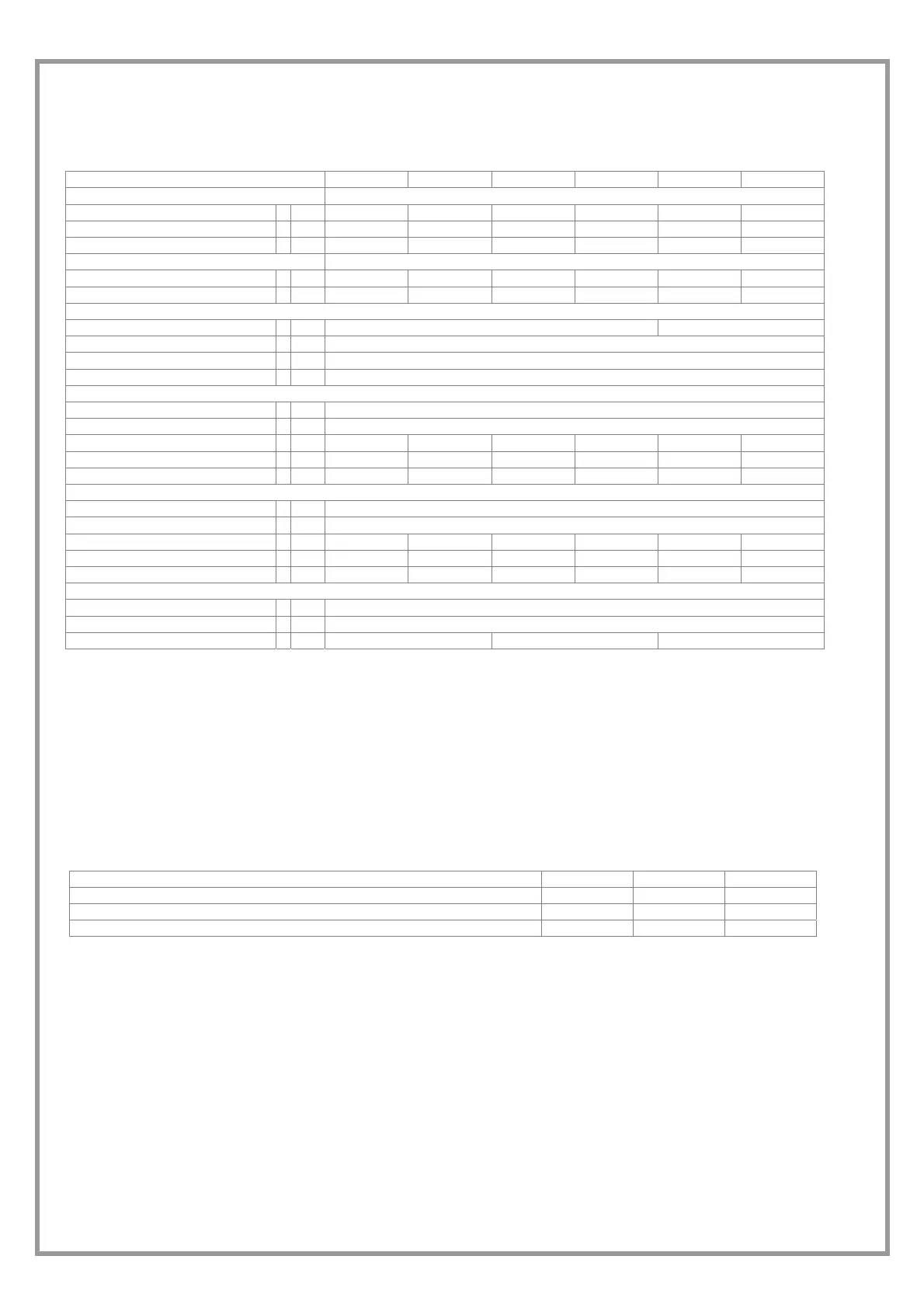
TECHNICAL DATA
Size 17 21 25 31 41 51
COOLING
Cooling capacity 1 kW 6,2 7,6 8,6 10,9 12,4 15,9
Sensible capacity 1 kW 5 5,8 7 8,6 9,5 12,5
Compressor power input 1 kW 1,7 2,1 2,2 2,9 2,8 3,8
HEATING
Heat output 2 kW 6,8 8,3 9,2 11,9 13,2 16,9
Compressor power input 2 kW 1,3 1,7 1,8 2,2 2 2,8
COMPRESSORS
Type of compressors 3 Rot Scroll
No. of Compressors 1
Std Capacity control steps 1
Refrigerant circuits 1
AIR HANDLING SECTION FANS (OUTLET)
Type of fans 4 CFG
Number of fans 1
Standard air flow l/s] 330 390 470 610 690 920
Installed unit power kW 0,3 0,3 0,4 0,4 0,6 0,6
Max outside static pressure 5 Pa 190 175 300 180 270 340
AIR HANDLING SECTION FANS (EXHAUST)
Type of fans 4 CFG
Number of fans 1
Standard air flow l/s 300 360 440 550 640 860
Installed unit power kW 0,3 0,3 0,4 0,4 0,6 0,6
Max outside static pressure 5 Pa 180 165 290 210 250 360
DIMENSIONS
Length mm 1503
Depth mm 950
Height mm 442 517 668
(1) exhaust coil inlet air temperature 27°C B.S. - 19°C B.U.
outdoor air temperature 35°C B.S. - 24°C B.U.
(2) exhaust coil inlet air temperature 20°C B.S. - 12°C B.U.
outdoor air temperature 7°C DB - 6°C WB
(3) SCROLL = scroll compressor
ROT = rotary compressor
(4) CFG = centrifugal fan
(5) Static pressure available on unit with electronic filters (excluding integration coil)
OVERLOAD AND CONTROL DEVICE CALIBRATION
On Of
alue
High pressure safety switch kPa 4200 3300 --
Low pressure safety switch kPa 300 450 --
Max no. of compressor starts per hour Nr -- -- 10