Do you have a question about the CLIVET CRH-XHE2 49.4 and is the answer not in the manual?
Provides instructions for unit installation, use, and maintenance.
Outlines requirements for qualified personnel to operate the unit.
Highlights potential hazards during operation and installation.
Specifies the unit's designed purpose and limitations.
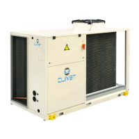
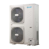
Details requirements for outdoor unit installation and local regulations.
Emphasizes planning periodic inspections to reduce costs.
Warns that modifications void warranty and manufacturer responsibility.
Instructs immediate deactivation and contacting authorized agents.
Lists key topics for user training by the installer.
Advises checking the manufacturer's website for updated data.
Guides on manual storage and recording interventions.
Explains the serial number label and its information.
States it uniquely identifies each unit and is needed for spare parts.
Instructs to note data from the serial number label for requests.
Advises observing external packaging instructions for storage.
Provides a step-by-step guide for safe unit handling and lifting.
Emphasizes careful removal of packaging to avoid unit damage.
Details spaces needed for unit operation, maintenance, and safety.
Lists criteria for selecting an installation place and avoiding airflow obstacles.
Installer's responsibility for drain tube installation per regulations.
Refers to Accessories section for details on the electronic filter.
Outlines water feature requirements and potential issues with inadequate quality.
Advises on measures to prevent freezing of connections in low temperatures.
Discusses the use and implications of anti-freeze solutions.
Specifies requirements for project water flow rate.
Stresses the importance of installing an accessible water filter for cleaning.
Guides on proper disposal of condensate to avoid damage.
Details the steps for hydraulic circuit operation and filling.
Refers to Accessories section for humidifier details.
Illustrates different methods for hydraulic connections.
Covers smooth internal surfaces, thermal isolation, and diffuser placement.
Explains where to find unit electrical data and matriculation plate information.
Lists essential steps for safe electrical connection procedures.
Provides guidelines for laying signal and data cables to avoid interference.
Advises on fixing cables and preventing contact with hot components.
Details customer-provided connections and terminal assignments.
Explains settable input modes for Fan and mode control.
Guides on connecting a PC for unit configuration and data access.
Illustrates options and distances for remote control units.
Details cable requirements and installation for Modbus/RS485 communication.
Specifies cable types and specifications for LonWorks communication.
Describes Ethernet connections and status indicators for BACnet IP.
Emphasizes qualified technician involvement and pre-checks before starting.
Lists checks for unit power supply, spaces, and components before start-up.
Details steps for powering on the unit, including voltage and fan checks.
Guides on checking the refrigeration circuit for pressure and leaks.
Advises on ensuring the hydraulic system is clean, filled, and vented.
Covers grounding, conductor tightening, voltage, and phase balance checks.
Instructs connecting heaters 8 hours before start-up.
Recommends checking operating temperatures and unit voltage.
Notes that scroll compressors have only one rotation direction.
Advises checking connections for remote controls and optional components.
Guides on setting unit flow rate based on aeraulic system features.
Explains standard, ECO, and variable airflow modes.
Describes ECO mode for energy saving and thermal maintenance.
Explains how setpoints adjust automatically with outside temperature.
Details unit's ability to maintain ambient pressure via outdoor air damper.
Outlines standard and constant airflow options.
Explains how the unit manages fire alarm signals and related parameters.
Mentions setting the start-up ramp for the supply fan.
Describes features for cold climates and panel protection.
Explains limiting electric power via external signal 0-10V.
Guides on identifying operating conditions for long-term control.
Explains regulations for installation verification and setting certification.
Explains keypad functions and operational mode symbols.
Details MANUAL, AUTOMATIC, ECO, and FAN operational modes.
Covers manual and automatic temperature setpoint adjustments.
Guides on accessing and modifying unit parameters via password.
Explains how to access and view various unit status indicators.
Details procedures for setting date, time, and format.
Describes how to lock/unlock keypad buttons.
Guides on viewing and identifying ongoing alarms.
Explains how to enable and set up weekly schedules for unit operation.
Outlines common operations via the service keypad and display meanings.
Defines various display elements and their meanings.
Summarizes basic operations like ON/OFF, mode, and setpoint changes.
Illustrates navigation through the main menu for unit settings.
Details setting up daily events and values for the scheduler.
Guides on configuring HMI settings like backlight and contrast.
Explains visualizing, resetting alarms, and managing passwords.
Details steps for resetting the alarm log and accessing management options.
Describes the installer access menu and available parameters.
Lists unit alarms with their IDs, descriptions, and reset types.
Continues the list of unit alarms and their reset methods.
Details unit statuses, input/output variables, and their descriptions.
Lists thermoregulator statuses, parameters, and their functions.
Provides status information for circuit components and temperature sensors.
Lists statuses related to compressor discharge, source, and pressure sensors.
Details EEV valve status, communication protocols, and input statuses.
Emphasizes maintenance by authorized centers for efficiency and longevity.
Recommends periodic inspections based on unit usage frequency.
Advises creating a booklet to record unit interventions and troubleshooting.
Guides on preparing the unit for long periods of inactivity.
Highlights the importance of cleaning coils to prevent microorganism growth.
Stresses periodical cleaning of the basin to prevent clogging.
Details procedures for filter cleaning and replacement.
Refers to Accessories section for high efficiency air filter details.
Advises checking and cleaning the exchanger for optimal thermal exchange.
Specifies checking the closure and operation of crankcase heaters.
Mentions advanced scroll temperature protection features.
Advises checking the cleaning state, fastening, and corrosion of heaters.
Refers to Accessories section for humidifier details.
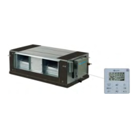
Illustrates how to access supply and exhaust fans.
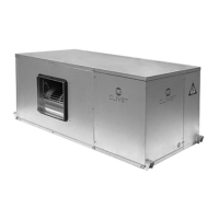
Shows how to access the unit's water circuit components.
Describes different unit configurations based on fan sections.
Illustrates hydraulic arrangements for constant flow-rate systems.
Illustrates hydraulic arrangements for variable flow-rate systems.
Shows hydraulic arrangements for systems with disposable water.
Covers humidifier connection, start-up, and maintenance.
Details supply water requirements and periodic checks for humidifiers.
Explains filter operation, maintenance materials, and ionisation wire care.
Guides on replacing pocket filters and disposing of old ones.
Outlines procedures for safely disconnecting the unit.
Mandates sending the unit to authorized centers for dismantling.
Explains regulations for proper disposal of electrical and electronic equipment.
Identifies common situations that could pose risks to people or things.
Warns about risks during unit handling without proper precautions.
Highlights potential issues like leaks, shocks, and poor operation from incorrect installation.
Covers risks from smoke, burns, and non-qualified maintenance personnel.
Details risks of shocks, fires, and electrocution from improper electrical work.
Warns about injuries from contact with transmissions or fans.
Addresses hazards from refrigerant expulsion and leaks.
Covers risks of leaks and water projection from tubing defects.
Provides cooling and heating capacities, power inputs, and efficiency ratings.
Lists sound power and pressure levels across different octave bands.
Shows the unit's operating limits for cooling based on air and water temperatures.
Displays the unit's operating limits for heating based on air and water temperatures.
Provides dimensions and weights for configurations 49.4-54.4.
Provides dimensions and weights for configurations 60.4-80.4.
Provides dimensions and weights for configurations 90.4-110.4.
| Category | Heat Pump |
|---|---|
| Model | CRH-XHE2 49.4 |
| Cooling Capacity | 49.4 kW |
| Power Supply | 400V / 3Ph / 50Hz |
| Refrigerant | R410A |