Do you have a question about the CLIVET CKN-XHE2i 14.2 and is the answer not in the manual?
Unit designed to prevent injuries; residual risks are detailed in a specific section.
Disable unit immediately, contact authorized agent, use original spares.
Check for damage and correspondence with transport documents before accepting delivery.
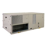
Consider technical spaces, connections, and air flow requirements for unit placement.
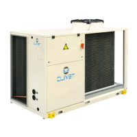
Install externally in fixed positions, limit vibration, choose a safe, accessible, and suitable location.
Proper disposal of condensate to avoid damage and prevent odors.
Dimensioning and execution of air connections for unit operation and silence.
Electrical line characteristics determined by qualified personnel, conforming to regulations.
Steps for making electrical connections, ensuring safety and correct wiring.
Details on external connections like ALC, HLVU, ALM, SA1, SA5, SA7, KPC, HLVE, HL1.
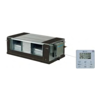
Information on what is needed and precautions for installing the room control.
Start-up operations by qualified technicians, agreement on data with service centre.
Checks before start-up: power supply, functional spaces, air flow, structure, filters, earthing.
Step-by-step sequence for unit start-up, including power supply and checks.
Check refrigerant circuit for oil stains, pressure, and ensure service outlets are closed.
Ensure water circuit is clean, filled, pressurized, and free of air.
Verify grounding, conductor tightness, voltage, frequency, and phase balance.
ECO mode for energy saving, maintaining thermal levels, renewal air not managed.
Setting the setpoint as fixed or variable based on outdoor temperature.
Configure unit behavior for fire alarm signals; unit is not a smoke extractor.
Set main operating parameters and access the alarm log for error codes.
A comprehensive list of error codes and their corresponding descriptions.
Modbus RTU protocol between controller and unit; controller is Master, Unit is Slave.
Details on Modbus RTU communication parameters: protocol, baud rate, data bits, parity, stop bit.
Exception codes for Modbus communication errors.
List of registers for mode setting, setpoints, airflow, and ECO mode.
Extensive table mapping fault codes (hex) to descriptions.
Maintenance by authorized centers to maintain efficiency and lifespan.
Schedule inspections every 6 months, frequency depends on use.
Cleaning the outdoor air coil to maintain thermal exchange and prevent damage.
Cleaning indoor air coils and condensate bowls to prevent microorganism growth.
Instructions for cleaning and replacing G4 filters; frequency depends on air quality.
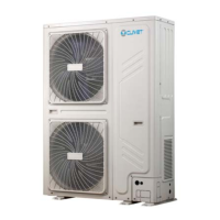
Technical specifications for cooling, heating, compressors, fans, and connections.
| Category | Heat Pump |
|---|---|
| Model | CKN-XHE2i 14.2 |
| Cooling Capacity | 14.2 kW |
| Refrigerant | R410A |
| Heating Capacity | 16.0 kW |
| Power Supply | 400V/3Ph/50Hz |
| Operating Temperature Range (Heating) | -20°C to 24°C |