Specifications
Page 18
ID2-XY 35M
0
8
4
1
2
3
5
6
7
C
9
A
B
D
E
F
1
2
ON
0
8
4
1
2
3
5
6
7
C
9
A
B
D
E
F
1
2
ON
0
8
4
1
2
3
5
6
7
C
9
A
B
D
E
F
1
2
ON
0
8
4
1
2
3
5
6
7
C
9
A
B
D
E
F
1
2
ON
S1+S2
0~F 0~F 0~F
0~F
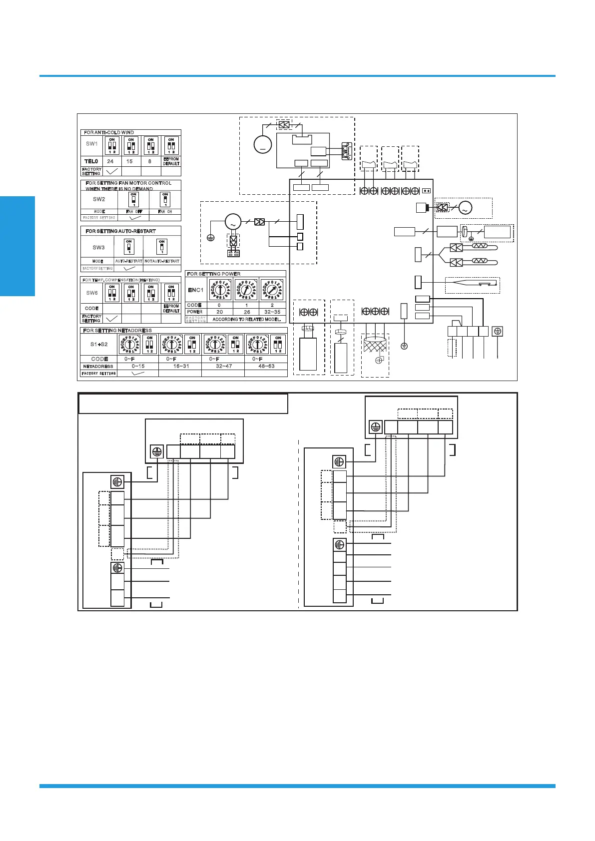
NETADDRESS
CODE
0~15
16~31
32~47
48~63
FACTORY SETTING
FOR SETTING NETADDRESS
INDOOR UNIT
MAINBOARD
CN33
ALARM
Alarm
Output
1
2
ON
1
2
ON
1
2
ON
1
2
ON
EEPROM
DEFAULT
FACTORY
SETTING
FOR TEMP. COMPENSATION(HEATING)
SW6
CODE
6℃
2℃
4℃
T2
T1
CN6
4
INDOOR COIL TEMP. SENSOR
ROOM TEMP. SENSOR
CN5
WATER LEVEL SWITCH
CN9
XYE
To CCM
Comm.Bus
Y/G
CN18
J7
CN23
ON/OFF
Remote
Control
CN43
FAN FOR THE
FRESH AIR
OR ANION
GENERATOR
NOTE:
1.The parts with dotted line indicates
optional features.
2.Remove the short connector of J7
when you use the "on-off" function.
AC FAN
CAP
Y/G
WHITE
WHITE
(GRAY)
CN4
P1
P2
BLACK
BROWN
M
5
3
FOR SETTING FAN MOTOR CONTROL
WHEN THERE IS NO DEMAND
1
ON
1
ON
SW2
FAN OFF FAN ON
MODE
FACTORY SETTING
1
2
ON
1
2
ON
1
2
ON
1
2
ON
SW1
TEL0
24
℃
15
℃
8
℃
EEPROM
DEFAULT
FACTORY
SETTING
FOR ANTI-COLD WIND
RED
CN2
CN1
BLACK
CN3
YELLOW
TO OUTDOOR UNIT
1(L)
2(N)
S
1
ON
1
ON
FACTORY SETTING
FOR SETTINGAUTO-RESTART
FOR SETTINGAUTO-RESTART
SW3
MODE
AUTO-RESTART
NOTAUTO-RESTART
0
8
4
1
2
3
5
6
7
C
9
A
B
D
E
F
0
8
4
1
2
3
5
6
7
C
9
A
B
D
E
F
0
8
4
1
2
3
5
6
7
C
9
A
B
D
E
F
ENC1
0
1
2
POWER
CODE
20
26
32~35
FACTORY
SETTING
ACCORDING TO RELATED MODEL.
FOR SETTING POWER
CN13
M
PUMP
2
REACTOR
CON2
RED
RED
DC MOTOR
DRIVER MODLE
CON1
FAN1
3
3
4
CN1
CN15
CN34
DC FAN
M
3
CN40
WIRE
R
4
MAGNETIC RING
HB HA
CN45
WIRE
R
MAGNETIC RING
DISPLAY
BOARD
WIRE
CONTROLLER
10
CN10
5
MAGNETIC RING
Y/G
16023000008781 WIRING DIAGRAM
W
RED
NOTE:
Please don't connect "W" if there
is no terminal in outdoor unit."W"
INDOOR UNIT
1(L)
2(N)
S
1
2
3
W
INDOOR UNIT
1(L)
2(N)
S
1
2
3
W
Air Condition Link-Circuit
Power supply:3-Phase 380-415V~
5-core cable 5x2.5mm
Power supply:3-Phase 220V~
5-core cable 5x4.0mm
2
2
1(L)
2(N)
S
L1
L2
L3
N
Power supply:
24K : 3-core cable 3x2.5mm
25K-36K : 3-core cable 3x4.0mm
37K : 3-core cable 3x6.0mm
1-Phase 208-240V~
≤
≥
2
2
2
1(L)
2(N)
S
If there is no Wterminal in outdoor unit:
4-core cable 4x2.5mm
(with auxiliary electric heater)
If there is aW terminal in outdoor unit:
“”
“”
4-core cable 4x1.0mm
5-core cable 5x1.0mm
5-core cable 5x2.5mm
(with auxiliary electric heater)
1
2
3
L(L1)
N(L2)
1
2
3
16022700002888
- - - - This symbol indicates the
element is optional,the actual
shape shall prevail.This wiring
diagram is just for mono;Don't
connect to W if there is no W
terminal in outdoor unit.
W
W
2
2
2
2
If there is no Wterminal in outdoor unit:
4-core cable 4x2.5mm
(with auxiliary electric heater)
If there is aW terminal in outdoor unit:
“”
“”
4-core cable 4x1.0mm
5-core cable 5x1.0mm
5-core cable 5x2.5mm
(with auxiliary electric heater)
2
2
2
2
 Loading...