Do you have a question about the CLIVET MV6-Xmi 252T-2700T Series and is the answer not in the manual?
Crucial safety instructions and warnings for proper handling and operation.
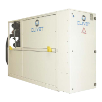
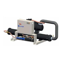
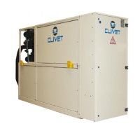
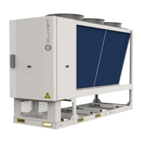
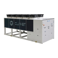
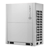
Identification and overview of the parts making up the outdoor unit.
List of included accessories for installation and use.
How to identify the outdoor unit via its serial number label.
Guidelines for selecting and combining outdoor and indoor units for system capacity.
Physical dimensions and weight of different outdoor unit models.
Configuration of master and slave units in multi-unit systems.
Climatic conditions for optimal cooling and heating operation.
Specifications for pipe dimensions for various unit models.
Maximum allowed lengths for refrigerant piping in different configurations.
Essential precautions and checks before commencing installation work.
Procedures for checking the product upon delivery for damage or discrepancies.
Guidelines for safe lifting, transport, and positioning of the unit.
Requirements for clearance and space around the unit for proper airflow.
Details on how to securely fix the unit to its base.
Instructions for installing ductwork for air management.
Steps for removing unit panels to access internal components.
Step-by-step guidelines for installing refrigerant piping.
Procedures and tables for determining correct pipe sizes for the system.
Essential electrical safety warnings and general connection guidelines.
Instructions for connecting the power supply, including cable selection.
Guidelines for installing the communication bus network and preventing interference.
Procedure for cleaning refrigerant pipes using nitrogen before operation.
Procedure for testing the system for refrigerant leaks after installation.
Steps for removing moisture and non-condensable gases from the system.
Instructions for charging the system with R410A refrigerant.
How to configure unit functions using dip-switches on the control board.
Setting the type of centralised controller to be used.
Configuring static pressure settings for fan operation.
Function to limit noise by adjusting compressor and fan operation.
Setting the unique address for each outdoor unit in the system.
Setting the unit's capacity for system configuration.
Defining operational priority for cooling or heating modes.
Methods for setting unit addresses (auto or manual search).
Configuring the number of connected indoor units.
Setting the network address for communication.
Navigating menus and viewing system parameters on the display.
Accessing and navigating different function menus via the control board.
Entering and viewing system control parameters and status.
Understanding parameters displayed on the unit's digital displays.
Listing and interpreting error codes for troubleshooting.
Essential checks and preparations before initial system start-up.
Procedures for testing and verifying system operation after installation.
Automatic process for assigning addresses to indoor and outdoor units.
| Model | MV6-Xmi 252T-2700T Series |
|---|---|
| Cooling Capacity | 252-2700 kW |
| Refrigerant | R134a |
| Power Supply | 400V/3Ph/50Hz |
| Compressor Type | Screw |
| Heat Recovery | Optional |
| IP Rating | IP54 |
| Type | Air-cooled chiller |
| Acoustic Configuration | Low noise |
| Operating Temperature Range | -10°C to 45°C |