Do you have a question about the CLIVET WSAT-XSC3 260.6-480.8 and is the answer not in the manual?
| Cooling Capacity | 260.6-480.8 kW |
|---|---|
| Refrigerant | R410A |
| Power Supply | 400V / 3Ph / 50Hz |
| Compressor Type | Scroll |
| Operating Temperature Range | -10°C to 45°C |
Details manual purpose, warnings, and prohibited operations for user safety and unit protection.
Specifies qualified personnel requirement for unit operation.
Discusses general risks during operation, installation, and maintenance by unqualified personnel.
Defines the unit's intended application for cooling/heating water or glycol mix.
Notes outdoor installation and responsibilities of the system designer.
Advises planning periodic inspections to avoid repair costs.
States that all unit modifications will void warranty coverage.
Instructions for immediate deactivation and contacting a service agent.
Outlines essential training topics for users by the installer.
Suggests visiting the manufacturer's website for updated product data.
Advises keeping the manual accessible and maintaining a unit notebook for interventions.
Explains how to identify the unit using the serial number label and matriculation plate.
States the serial number uniquely identifies each unit and is required for spare parts orders.
Guides on noting serial number data for efficient assistance requests.
Instructs to observe external packaging instructions for storage.
Provides detailed steps for verifying weight, identifying critical points, and safe unit handling.
Advises caution during packaging removal to avoid unit damage.
Defines functional spaces required for unit operation and maintenance.
Lists criteria for choosing the installation place and avoiding airflow obstructions.
Installer's responsibility for drain tubes per local regulations.
Visual reference for AxiTop component.
Refers to Accessories section for details on anti-vibration mounts.
Details water features and acceptable quality values to prevent issues.
Provides measures to protect the unit and connections from freezing temperatures.
Discusses the use of anti-freeze solutions and their impact.
Specifies requirements for project water flow-rate for optimal operation.
Highlights the importance of minimum system water volumes for compressor operation.
Describes different hydraulic connection methods and warnings.
States the installer must define component type and system position.
Specifies filter mesh pitch and installation requirements for cleaning.
Explains the necessity and installation of a flow switch for unit shutdown.
Details the sequence for filling and washing the hydraulic circuit to prevent damage.
Refers to Accessories section for hydronic assembly details.
Refers to Accessories section for energy recovery details.
Lists electrical data found on the serial number label and matriculation plate.
Provides a step-by-step guide for making electrical connections to the unit.
Gives guidelines for laying signal and data lines to avoid electromagnetic interference.
Details requirements for cable fixing and minimum distance from the ground for power input.
Provides table with cable section and torque specifications for main switch connections.
Lists connection points for customer wiring and signals.
Instructions for using the remote ON-OFF function.
Step-by-step guide for configuring PC connection and network settings.
Details options and wiring for remote control systems.
Covers Modbus/RS485 cable requirements and connection setup for communication.
Describes LonWorks cable specifications and LED indicators.
Describes BACnet IP cable specifications and LED indicators.
Overview of start-up operations, technician requirements, and preliminary checks.
Lists essential checks to perform before powering the unit.
Step-by-step procedure for starting the unit after installation.
Details checks for the refrigeration circuit, including oil stains and pressure.
Covers checks for the water circuit, filling, pressurization, and cleaning procedures.
Outlines checks for grounding, conductor tightness, voltage, and phase balance.
Instructions for connecting and checking compressor crankcase heaters.
Advises checking the connection and enabling of remote controls and probes.
Details checks for operating voltages and electrical absorptions.
Explains how to access and configure the demand limit parameter.
Describes the configuration of climatic text correction curves for setpoint adjustment.
Details the water reset correction feature and its parameter configuration.
Explains the ECOSHARE function for managing multiple units in a network.
Describes operation mode A for networked units.
Describes operation mode B for networked units.
Describes operation mode C for networked units.
Covers checks for evaporator water flow-rate and pressure drops.
Explains the inverter-driven variable flow-rate option.
Notes on scroll compressor rotation direction and potential issues.
Discusses risks associated with prolonged operation at reduced load.
Lists essential operating data to record during unit start-up.
Mentions instructions related to the 2014/68/UE PED directive.
Describes the function of LED indicators on the control panel.
Lists and describes the variables displayed on the unit's interface.
Explains the function of each key on the control panel for operation.
Guides on how to change the unit's operational state (OFF, ECO, ON, Pump On).
Details the procedure for changing the unit's operating mode between Cool and Heat.
Explains how to modify various setpoint values for cooling and heating.
Covers setting up weekly operational events and enabling the scheduler.
Describes how to display the unit's current operational status.
Lists general status parameters related to unit mode, alarms, and recovery.
Lists status parameters related to user-side pumps, inverters, and flow requests.
Lists status parameters for source pumps, inverters, and their operating hours.
Lists status parameters for circuit 1, including schema, subcooling, and pressure.
Lists all digital inputs available on the unit.
Lists all analogic inputs available on the unit, including temperatures and pressures.
Lists the unit's analog outputs for bypass, pumps, heaters, and valves.
Lists analogic outputs related to free-cooling, recovery pumps, and fans.
Details how to configure keyboard settings and behavior.
Explains how to identify, reset, and manage unit alarms.
Lists common electrical circuit alarms, their descriptions, and categories.
Lists common alarms related to refrigerant circuits, including pressure and temperature issues.
Lists common alarms related to hydraulic circuits, such as water pressure and flow issues.
Outlines general maintenance principles, safety checks, and advice for performing maintenance.
Recommends creating a unit booklet to record interventions and aid troubleshooting.
Provides instructions for putting the unit in standby mode and for its re-start.
Details the recommended frequency for various inspections based on unit usage.
Emphasizes the importance of keeping the water side exchanger clean for thermal exchange.
Lists checks for circulating pumps, including leaks and bearing status.
Advises checking the water filter for impurities that might obstruct water passage.
Explains the procedure for cleaning the air coil and verifying fin condition.
Provides instructions regarding the compressor supply line shut-off valve.
Mentions flow switch controls operations and removing incrustations.
Outlines checks for crankcase heater closure and operation.
Mentions advanced scroll temperature protection.
Lists checks for electric fans, protection grids, and bearings.
Advises checking the condition of unit insulations.
Provides steps for system discharge, including evacuation and fluid disposal.
Illustrates the procedure for replacing a compressor on the unit.
Shows visual guides for replacing heat exchangers.
Shows visual guides for replacing pumps on the unit.
Lists various anti-vibration mount supports with their specifications and codes.
Explains the function of partial energy recovery for hot water production.
Describes the total energy recovery configuration for producing hot water.
Details the diagrams and components of the storage tank system.
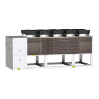
Introduces the HydroPack pumping unit and its modular logic activation.
Describes the Hydropack unit configured with 6 inverter pumps.
Provides instructions for safely disconnecting the unit and recovering fluids.
Covers unit dismantling, proper disposal methods, and compliance with national standards.
Explains the manufacturer's compliance with EC RAEE directive for waste equipment.
Identifies common situations that cannot be controlled and may pose risks.
Details risks associated with electrical connections, components, and earthing.
Highlights hazards from contact with moving parts like fans and transmissions.
Discusses risks related to refrigerant handling, safety valve operation, and potential explosions.
Covers risks associated with tubing defects, attachments, and water projection.
Presents performance data tables for the Excellence version units.
Details performance data for Excellence SC configuration units.
Details performance data for Excellence EN configuration units.
Presents construction data tables for the Excellence version units.
Lists sound power and pressure levels for Excellence version units across various configurations.
Displays operating range graphs for Excellence version units based on temperatures.
Presents performance data tables for the Premium version units.
Details performance data for Premium SC configuration units.
Details performance data for Premium EN configuration units.
Provides detailed construction specifications for the Premium version units.
Lists sound power and pressure levels for Premium version units across various configurations.
Displays operating range graphs for Premium version units based on temperatures.