Do you have a question about the CLIVET WSAT-XIN 171 and is the answer not in the manual?
Highlights potential hazards during operation, installation, maintenance, and repair by inexperienced personnel.
Covers system designer's role in positioning, hydraulics, electrics, and ducting according to local regulations.
Instructs to disable unit immediately, contact authorized service, and use original spare parts.
Lists criteria for installation location, including external placement, fixed positions, vibration limits, and avoiding obstructions.
Details required water features, limits for corrosion, and consequences of inadequate water quality, advising treatment systems.
Outlines measures to prevent freezing in the unit or connections, such as using glycol or heating cables.
Specifies project water flow requirements for exchanger operating limits and system conditions.
States installer must define component type and position, and provides a diagram for recommended connections.
Lists steps for making electrical connections, emphasizing isolation, earth connection, and protection restoration.
Illustrates power input connections and offers advice on installing an isolator switch and cable routing.
Shows diagrams of electrical panels for different unit sizes and lists component functions.
Provides electrical panel connection diagrams for customer-performed connections for various unit sizes.
Outlines start-up operations to be performed by qualified technicians and installer responsibilities for connections.
Lists essential preliminary checks before unit start-up, covering power, functional spaces, and system integrity.
Details the step-by-step sequence for unit start-up after power ON, including voltage, fan, and temperature checks.
Instructs to check the refrigeration circuit for oil stains, pressure, and valve status, and to open valves if present.
Covers checks for the hydraulic system's cleanliness, pressure, shut-off valve positions, and air evacuation.
Emphasizes verifying grounding, conductor tightness, and phase balance, providing examples and warnings.
Lists alarm codes, descriptions, and types, providing a reference for troubleshooting.
Explains how to set up to three different schedulings, associate events, and assign them to days of the week.
Recommends inspections every 6 months, with shorter intervals for frequent or critical use.
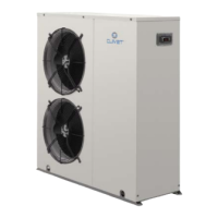
Illustrates and labels the main components of the unit for different sizes (21-71).
Lists alarm codes, descriptions, and types, providing a reference for troubleshooting.
Details specific alarm codes related to the electronic thermostatic driver, including faulty probes and circuit issues.
Provides a menu-driven overview of unit status parameters like temperatures, pressures, and operational states.
Details the RCTX remote control, its dimensions, and connection diagram.
Describes the CMSC2X module for serial communication, its installation, and cable characteristics.
Explains the KG4UP kit for managing multiple units in parallel, including scheduling examples.
Details risks associated with incorrect installation, including leaks, electric shock, and structural damage.
Highlights risks related to electrical connections, components, earthing, and moving parts causing shocks or injuries.
Warns about injuries from contact with transmissions or fan aspiration, requiring isolator use.
Warns about refrigerant risks from safety valve expulsion, contact with heat sources, or welding operations.
| Cooling Capacity | 169 kW |
|---|---|
| Refrigerant | R410A |
| Sound Power Level | 91 dB(A) |
| Power Supply | 400V/3Ph/50Hz |
| Operating Temperature Range | -10°C to 45°C |
| EER | 3.10 |