Do you have a question about the CLIVET WDH-3 2.280 and is the answer not in the manual?
Describes the label and its purpose, including type of unit, serial number, year of manufacture, electrical diagram, data, logo, and address.
Unit must be installed, tested, and maintained by expert personnel meeting legal requirements.
Installation must be performed observing all local safety regulations.
Ensure power supply conforms to data on the unit's rating plate.
Disconnect power before service operations and follow local regulations.
Perform inspections to locate loose/broken parts to prevent damage and injury.
Switch off the unit immediately in the event of faults or poor operation.
Repairs must be carried out by authorized centers using original spare parts.
Unauthorized modifications void the warranty and manufacturer's responsibility.
The unit must only be used for the specific purpose it was designed for.
Unit designed to prevent risks; refer to Residual Risks section for guidance.
Products bear the CE mark, complying with relevant EC directives and national legislation.
Defines internal and external danger zones around the unit where specific personnel may operate.
Incorrect installation can cause leaks, shocks, fire; must be by qualified technician.
Covers risks like burning smells, contact with hot parts, unskilled repairs, and loose panels.
Risks of shock, fire, damage from incorrect supply, loose covers, or poor earthing.
Outlines health effects and physical/chemical dangers of the substance.
Provides instructions for inhalation, skin contact, eye contact, and physician guidance.
Details specific dangers, intervention means, and protection systems for fire prevention.
Covers individual precautions and measures for enclosed spaces during spills.
Specifies exposure limits, personal protective equipment, and hygiene measures.
Covers acute toxicity, local effects, sensitization, chronic toxicity, carcinogenicity, and reproductive toxicity.
Check unit for transit damage upon arrival; note any deficiencies on the delivery document.
Follow safety norms; value critical points; check lifting capacity for safe handling.
Instructions for lifting the unit using a crane, including pipe and belt positioning.
Respect functional clearances for unit operation, maintenance, and operator safety.
Electrical lines and components must be designed and installed by specialized personnel adhering to regulations.
Verify unit installation, electrical power supply, sectioning device, and presence of tension before starting.
Check for oil stains, circuit pressure, and ensure service outlets are properly capped.
Ensure plumbing is washed, circuit filled/pressurized, check seals, valves, and air presence.
Check fluid temperatures, supply tension, phase unbalance, and total unit absorption.
Connect oil resistances at least 8 hours before starting the compressor.
Open compressor cocks, if present, and switch off the isolator switch.
Check screw tightness, ground connection, panels, and verify power supply values.
Instructions on how to turn the unit on/off and access different operating menus.
Explains thermal regulation based on inlet temperature and compressor insertion logic.
Schedule inspections annually or semi-annually; perform specific checks.
Lists common causes for high-pressure alarms in cooling mode, such as water temperature or flow issues.
Lists common causes for low-pressure alarms in cooling mode, such as water temperature or flow issues.
Steps to identify and resolve issues related to faulty probes, including checks and replacement.
Steps to identify and resolve issues related to faulty pressure transducers.
Lists possible causes for compressor protection alarms, such as high discharge temperature.
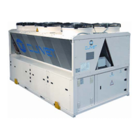
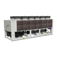
Provides technical specifications for cooling mode, including capacity, power input, EER, and ESEER.
Provides technical specifications for heating mode, including heat output, power input, and COP.
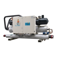
Details compressor type, number, rated power, and oil charge.
Provides data on internal exchanger water flow, pressure drop, and water content.
Provides data on external exchanger water flow, pressure drop, and water content.
Specifies maximum and minimum temperature limits for exchangers for Efficiency Class B.