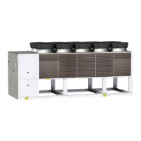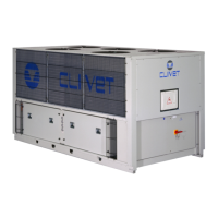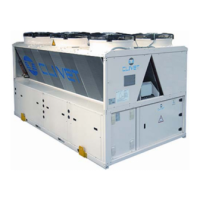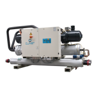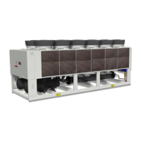
Do you have a question about the CLIVET WDAT-SL3 FC Series and is the answer not in the manual?
Provides instructions for unit installation, use, and maintenance.
Details potential hazards and the need for qualified personnel.
Guidelines for unit positioning, system design, and electrical checks.
Instructs immediate unit disabling and contacting a service agent.
Manual storage, unit data label, and breakdown procedures.
Explains the serial number label and its information.
Details steps for safe lifting and handling of the unit.
Defines required spaces for unit operation and maintenance.
Criteria for selecting installation location and avoiding airflow issues.
Specifies acceptable water quality limits and potential issues.
Outlines measures to prevent freezing in low temperatures.
Ensures shutdown if water is not circulating.
Steps for making electrical connections, ensuring safety.
Details cable sizes and tightening torques for various unit sizes.
Steps for connecting and configuring a PC for unit control.
Information on Modbus/RS485 communication and cable requirements.
Outlines operations done by qualified technicians for start-up.
Steps for unit ON power supply and initial operation checks.
Verifies grounding, conductor tightening, voltage, and phase balance.
Limits absorbed electric power via external signal.
Automatic management of multiple units in a network.
Explains variables shown on the display and their meanings.
Lists control panel keys and their functions.
Instructions for adjusting setpoints for different operating modes.
Procedures for identifying, resetting, and managing unit alarms.
Recommends inspection intervals based on unit usage frequency.
Importance of clean exchanger surfaces and cleaning procedures.
Instructions for cleaning the air coil to maintain thermal exchange.
Procedures for safely evacuating the system and its components.
Identifies status codes and parameters for central module signals.
Details status codes for compressor, pressure, and valve signals in Circuit 1.
Diagrams and conditions for direct free-cooling operation.
Configuration for producing hot water during cooling mode.
Configuration for producing hot water and chilled water simultaneously.
Pumping unit with auto-adaptive logic for liquid flow rate reduction.
Procedures for safely disconnecting the unit and recovering fluids.
Guidelines for sending the unit to authorized centers for disposal.
Identifies common risk situations related to general, electric, and hydraulic aspects.

