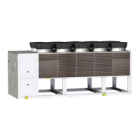
FCD / FCI CONFIGURATION
Acoustic conguration: compressor soundproong (SC)
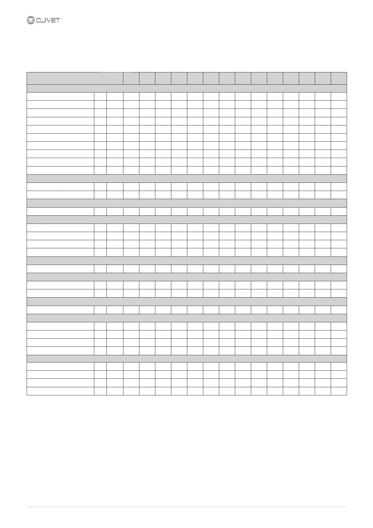
General technical data - Construction
Size 200.2 210.2 220.2 240.2 260.2 280.2 320.2 340.2 360.2 400.2 440.2 500.2 540.2 580.2
Compressor
Type of compressors 1 - DSW DSW DSW DSW DSW DSW DSW DSW DSW DSW DSW DSW DSW DSW
No. of compressors Nr 22222222222222
Rated power (C1) [HP] 100 100 110 120 120 140 160 160 180 200 220 250 270 290
Nominal capacity (C2) [HP] 100 110 110 120 140 140 160 180 180 200 220 250 270 290
Std Capacity control steps
6 25-100% 25-100% 25-100% 25-100% 25-100% 25-100% 25-100% 25-100% 25-100% 25-100% 25-100% 25-100% 25-100% 25-100%
Oil charge (C1) [l] 17 17 17 17 17 21 21 21 25 25 25 25 30 30
Oil charge (C2) [l] 17 17 17 17 21 21 21 25 25 25 25 25 30 30
Refrigerant charge (C1) [kg] 72 72 69
80 80 97 97 95 108 124 126 142 160 161
Refrigerant charge (C2) [kg] 69 69 69 80 81 97 97 114 114 130 135 150 169 170
Refrigeration circuits - 22222222222222
Internal exchanger (evaporator)
Type of internal exchanger 2 - S&T S&T S&T S&T S&T S&T S&T S&T S&T S&T S&T S&T S&T S&T
N. of internal exchanger Nr 11111111111111
External exchanger (condenser)
Frontal surface m² 18,7 18,7 23,4 23,4 23,4 28,1 28,1 32,8 32,8 37,4 37,4 46,8 46,8 46,8
External Section Fans
Type of fans 3 - AX AX AX AX AX AX AX AX AX AX AX AX AX AX
Number of fans Nr 8 8 10 10 10 12 12 14 14 16 16 20 20 20
Type of motor 4 - AC/P AC/P AC/P
AC/P AC/P AC/P AC/P AC/P AC/P AC/P AC/P AC/P AC/P AC/P
Standard airow [l/s] 42160 42160 52700 52700 52700 63250 63250 73800 73800 84300 84300 105400 105400 105400
Connections
Water ttings - 8” 8” 6” 6” 6” 6” 6” 6” 6” 8” 8” 8” 8” 8”
Water content
Water content FCD [l] 671 672 827 827 829 866 865 951 951 1237 1237 1635 1635 1635
Water content FCI [l] 409 409 436 442 449 470 475 541 551 975 997 885 894 905
Power supply
Standard power supply
-
400/3~/50 400/3~/50 400/3~/50 400/3~/50 400/3~/50 400/3~/50 400/3~/50 400/3~/50 400/3~/50 400/3~/50 400/3~/50 400/3~/50 400/3~/50 400/3~/50
Electrical data - FCD
F.L.A. - Total
A 369,7 387,9 414,3 439,7 488,5 545,5 599,5 647,5 687,3 751,3 819,3 916,3 982,3 1047,1
F.L.I. - Total
kW 225 236,3 251,5 267,5 292,3 321 352,8 381 405,3 442,4 493,4 545,4 594,2 634,2
M.I.C. - Value
5 A 355,9 408,9 426,7 436,2
432,2 472,9 559,2 657,3 687,1 712,1 808,6 956,1 1095,8 1253,1
M.I.C. - with soft start accessory
5 A 516,9 597,9 615,7 630,2 615,2 655,9 786,2 978,3 1008,1 1034,1 1167,6 1380,1 1668,8 1853,1
Electrical data - FCI
F.L.A. - Total
A 387,1 405,3 431,7 457,1 505,9 562,9 620,3 668,3 714,5 778,5 846,5 956,7 1022,7 1087,5
F.L.I. - Total
kW 233 244,3 259,5 275,5 300,3 329 363,8 392 420,3 457,4 508,4 567,4 616,2 656,2
M.I.C. - Value
5 A 355,9 408,9 426,7 436,2 432,2 472,9 559,2 657,3 687,1 712,1 808,6 956,1 1095,8 1253,1
M.I.C. - with soft start accessory
5 A 516,9 597,9 615,7 630,2 615,2 655,9 786,2 978,3 1008,1 1034,1 1167,6 1380,1 1668,8 1853,1
Sound
1. DSW = double screw compressor
2. S&T = shell and tube
3. AX = axial fan
4. AC/P = asynchronous three-phase external rotor motor with phase cutting speed automatic control
Unbalance between phase max 2 % Voltage variation: max +/- 10%
Electrical data refer to standard units; according to the installed accessories, the data can suer some variations.
5. M.I.C. = compressor 2 starting current + compressor 1 current at 75% of the max load + circuit 1 fan
6. The unit is able to modulate STEPLESS continuously. The following data refers to a continuous operation of the
unit. During start-up and stop, each compressor is able to modulate up to 25% of its capacity
 Loading...