12 WSA-XEE 122-402
M02S40N16-00
4.5 Operation sequence
Close all vent valves in the high points of the unit hydraulic circuit
Close all drain valves in the low points of the unit hydraulic circuit:
•
Heat exchangers
•
Pumps
•
collectors
•
storage tank
•
free-cooling coil
1. Carefully wash the system with clean water: ll and drain the system several times.
2. Apply additives to prevent corrosion, fouling, formation of mud and algae.
3. Fill the plant
4. Execute leakage test.
5. Isolate the pipes to avoid heat dispersions and formation of condensate.
6. Leave various point of service free (wells, vent-holes etc).
Neglecting the washing will lead to several lter cleaning interventions and at worst cases can cause damages to the exchangers and the
other parts.
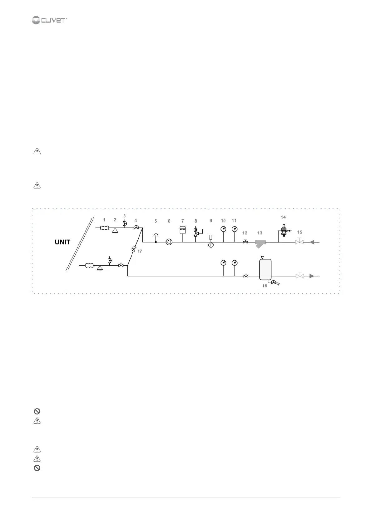
4.6 Recommended connection
The installer must dene:
•
component type
•
position in system
1 antivibration joints 10 pressure gauge
2 piping support 11 thermometer
3 exchanger chemical cleaning bypass 12 shut-o valve
4 shut-o valve 13 lter
5 vent 14 lling valve
6 Pump / circulating pump 15 shut-o valve
7 expansion vessel 16 Internal storage tank
8 safety valve 17 Cleaning system bypass
9 Flow Switch
4.7 Hydraulic connections
•
take away the supplied connection union by acting on the connection joint
•
weld the union to the installation pipe
•
perform the connection between the installation pipe and the evaporator, using the joint
Retirer le joint de connexion avant de souder le tuyau de l’installation.
The rubber gasket might be irreparably damaged.
4.8 Water lter
Use lter with mesh pitch of 1,6 mm
It must be installed immediately in the water input of the unit, in a position that is easily accessible for cleaning.
The lter never should be removed, this operation invalidates the guaranty.