EasyManua.ls Logo

CLIVET WSAT-XEE 222 User Manual

CLIVET WSAT-XEE 222
44 pages
To Next Page IconTo Next Page
Page #1 background imageLoading...
Page #1 background image
WSAT-XEE 82-102-122-162-
182-222-262-302
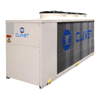
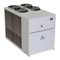
AIR COOLED WATER CHILLER FOR OUTDOOR INSTALLATION
Installation and Use Manual
M0G140F7-01 06/11/07
Question and Answer IconNeed help?

Do you have a question about the CLIVET WSAT-XEE 222 and is the answer not in the manual?

CLIVET WSAT-XEE 222 Specifications

General IconGeneral
BrandCLIVET
ModelWSAT-XEE 222
CategoryChiller
LanguageEnglish

Summary

UNIT IDENTIFICATION

SERIAL NUMBER

Unique machine identifier for tracing specific features and components.

USER INSTRUCTIONS

COMMON CAUSES OF SHUTDOWN

Lists typical reasons for unit malfunction or unexpected shutdown.

GENERAL WARNINGS AND SAFETY

INTENDED USE AND PRECAUTIONS

Specifies the unit's designed purpose and crucial safety precautions.

RESIDUAL RISKS

DANGER ZONES AND HANDLING RISKS

Identifies hazardous areas around the unit and risks during handling operations.

ELECTRICAL SYSTEM RISKS

Highlights potential dangers and safety requirements for the unit's electrical system.

RESIDUAL RISKS (continued)

MOVING PARTS AND REFRIGERANT HAZARDS

Warns about injuries from moving parts and hazards of refrigerant exposure.

POSITIONING GUIDELINES

UNIT PLACEMENT AND FIXING

Recommendations for secure unit installation, anti-vibration devices, and windbreaks.

WATER CONNECTIONS

ELECTRICAL CONNECTION

GENERAL GUIDELINES AND DATA

Essential electrical data, safety, and connection procedures for the unit.

FUNCTIONAL CONNECTIONS

START-UP PROCEDURES

PRELIMINARY CHECKS AND SYSTEM PREP

Essential checks for installation, power supply, and system readiness.

ELECTRICAL AND COMPRESSOR CHECKS

Verifying electrical connections, tensions, and compressor crankcase heaters.

UNIT CHECKS AND PARAMETERS

CONTROL SYSTEM OPERATIONS

SET-POINT COMPENSATION METHODS

How set-point compensations affect compressor activation and system performance.

SET-POINT MANAGEMENT

PARAMETER AND STATUS VIEWING

ALARMS AND SIGNALS

ALARM RESET AND CAUSE IDENTIFICATION

Procedures for safely resetting alarms and identifying their root causes.

PRE-ALARMS, SIGNALS, AND FAULTS

Differentiating between pre-alarms, signals, and faults for proper response.

ALARM VISUALIZATION

ALARM LOG AND DISPLAY

How to view and interpret the unit's alarm log, including flashing codes and timestamps.

ROUTINE MAINTENANCE

INSPECTION AND STANDBY PROCEDURES

MAINTENANCE INSPECTIONS AND CE DIRECTIVE

Guidelines for periodic inspections, manufacturer instructions, and CE PED directive.

REFRIGERANT DATA AND TABLES

TROUBLESHOOTING GUIDE

PRESSURE AND PROBE ALARMS

Diagnosing issues related to high/low pressure, faulty probes, and transducers.

TRANSDUCER AND CIRCUIT FAULTS

Troubleshooting pressure transducers and identifying refrigerant circuit faults.

COMPONENT PROTECTION AND FAULTS

COMPRESSOR, FAN, AND PUMP PROTECTION

Identifying and resolving protection faults for compressors, fans, and pumps.

UNIT DIMENSIONS

UNIT DIMENSIONS (continued)

Related product manuals