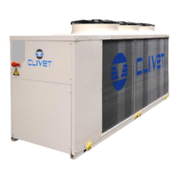
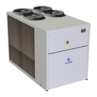
Do you have a question about the CLIVET WSAT-XEE 262 and is the answer not in the manual?
Provides unique identification for tracing unit features and components. Essential for requesting assistance.
Lists common reasons for unit shutdown, such as dirty coils, incorrect set points, and fan blockages.
Procedure to view alarms, access the alarm log, and reset alarms after cause elimination.
Specifies that installation, testing, and maintenance must be done by expert personnel meeting legal requirements.
Highlights design solutions to prevent hazards and reduce risks to persons and health.
Highlights areas where only authorized personnel may operate, distinguishing between internal and external danger zones.
Safety procedures for handling the unit to prevent falls, topples, and damage to persons or property.
Details risks of incorrect installation, emphasizing qualified technicians and local regulations.
Covers risks like burning smells, smoke, contact with hot parts, unskilled repairs, and panel security.
Warnings about power supply connections, earth connection, and contact with live parts.
Precautions for avoiding injury from contact with fan rotors, including power disconnection.
Information on risks from refrigerant gas escaping, contact with flames, and welding operations.
Risks associated with water leaks, spray, and damage caused by defects in hydraulic connections.
Detailed safety information for R-410A refrigerant, including composition, hazards, first aid, and handling.
Information on local effects, long-term toxicity, and specific effects like freezing and cardiac arrhythmia.
Procedure for checking the unit for damage during transit and ensuring completeness upon arrival.
Guidelines for safe handling operations, considering critical points, lifting capacity, and unit balance.
Factors to consider for air-conditioning system installation, including technical spaces and connections.
Importance of respecting functional clearances for unit operation, maintenance, and operator safety.
Advice on anchoring, avoiding obstacles, ensuring air circulation, and preventing stratification.
Measures to prevent freezing, including glycol mixing and using heating cables.
Requirements for electrical lines and components, emphasizing specialized personnel and safety.
Presents electrical data like FLA, FLI, MIC for different unit sizes, and power supply details.
Step-by-step instructions for connecting the unit to the main power supply, including checks.
Checks to perform before starting the unit, including installation, power supply, and component cleanliness.
Verifying the refrigerating circuit for oil stains, pressure, and proper closure of service outlets.
Ensuring the plumbing system is washed, filled, pressurized, and that shut-off valves are open.
Checking screw tightening, ground connection, panel repositioning, and voltage/frequency limits.
Checking fluid temperatures, working limits, and electrical parameters during operation.
Taking note of operational data like discharge temperature, pressure, and liquid temperature.
Steps for modifying parameters using the SET button, selecting parameters, and modifying values.
Information on alarm causes, manual reset procedures, and the difference between pre-alarms and faults.
Table listing alarm codes (E/S/S/E), their description, and reset type (Auto/Manual).
Recommendations for preparing the unit for long periods of inactivity, especially for winter.
Lists causes for high pressure alarms, including high temperatures, dirty coils, and fan issues.
Lists causes for low pressure alarms, including low temperatures, poor flow, and refrigerant issues.
Details causes of compressor protection activation, including electrical issues and high discharge temperature.
Procedure for disconnecting the unit, including recovering refrigerant and antifreeze.
Settings for high/low pressure switches, antifreeze protection, and compressor start limits.
Maximum and minimum air intake temperatures for the external exchanger.
Maximum and minimum water supply temperatures for the internal exchanger.


