go green pay less no mess
7. TANK SUPPORT.
The composting tank must be supported by either packed earth with the
tank placed on a base of sand, or a wooden frame on a solid base; e.g. a
concrete slab. Insulation between the tank and the concrete slab will reduce
heat loss and aid the composting process.
NOTE: The tank and enclosure should be protected from surface and
floodwater.
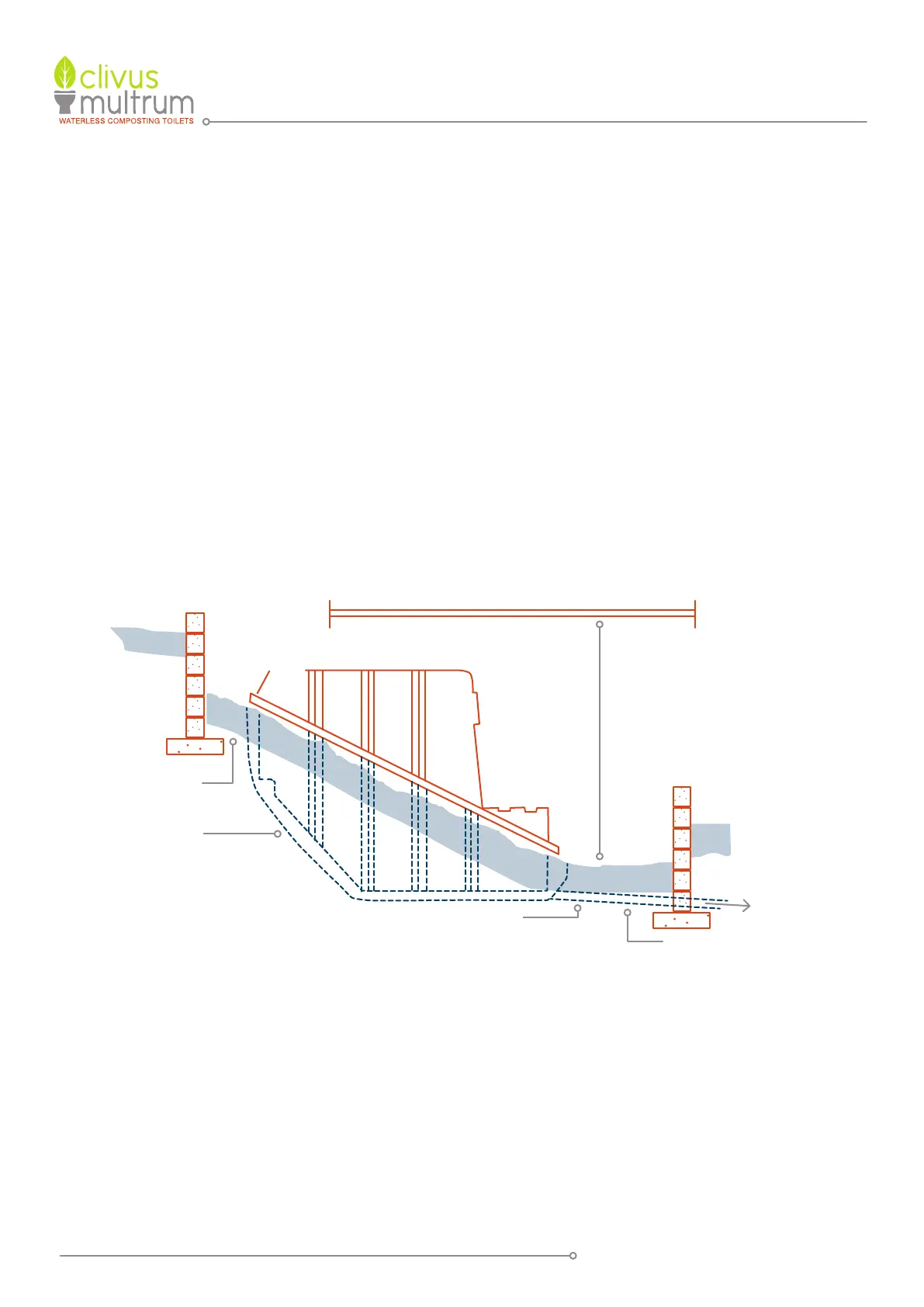
7.1 EARTH SUPPORT [SEE FIGURE 2].
The surface must be rock free and smooth to prevent possible puncture of
the tank. Stand the tank on 50-75 mm thick bed of sand, crusher dust fines
or similar. To avoid excessive soil pressure on the tank, the CM8 and CM10
can be buried only up to the tank join line, and the larger tanks should only
be buried to a maximum depth of 500mm.
In order to ensure stability of the surrounding earth, a retaining wall may be
required. All back fill around the tank should be rock free. When the tank
is partially dug into the ground, take steps to ensure that heavy rain will
not cause a build up of surface water in the area around the tank Ensure
the tank cannot slide forward by mounding sand or gravel around the front
of the tank as in Figure 2 above. Ensure that the position for liquid end-
product drain and trench has been marked.
SLOPING SITE INSTALLATIONS
Earth
Backfill
Sand
Layer
Tank
Drain
Ground & Surface
Water Drain
See table for
minimum floor
clearance
FIGURE 2
PAGE 8