5
TWO SPRING SYSTEM
Slide the spring(s), drums, winding unit(s), and
end bearing support (if supplied) onto the tor-
sion tube as shown in Figures 6 and 7. Alignment
may be required before the tube will pass through
spring spacer inside the spring.
If you have one spring see Figure 6 for the con-
guration of the components on the torsion tube.
The spring with "L-GREEN" stenciled on it and
green components MUST be put on the left side
of the tube. Make sure the end bearing support is
oriented so that the bearing is facing toward the
right drum.
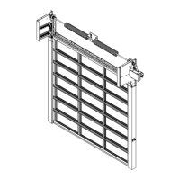
If you have two springs see Figure 7 for the
conguration of the components on the torsion
tube. The spring with "L-GREEN" stenciled on it
and green components MUST be put on the left
side of the tube and the spring with "R-ORANGE"
stenciled on it and orange components MUST be
put on the right side of the tube. The torsion tube
coupler will be located between the two springs if
so equipped.
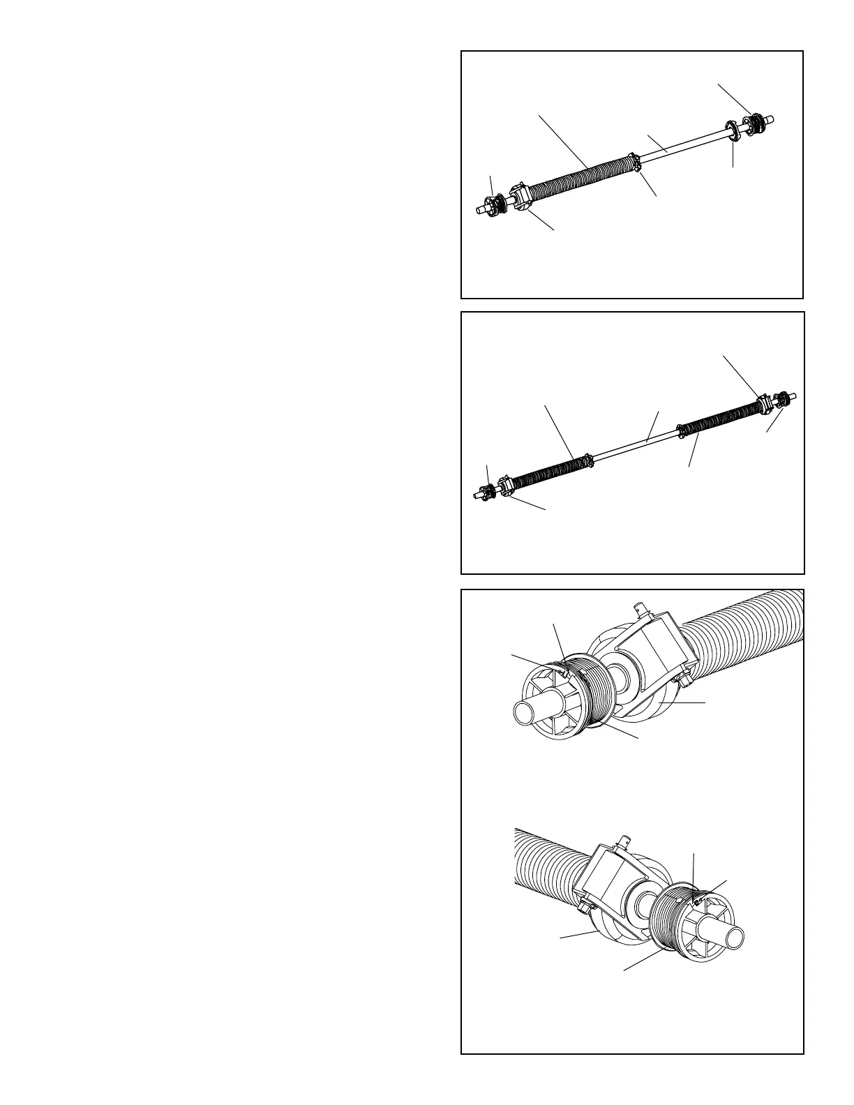
The drums should be oriented so that the slots are
facing away from the winding unit(s) and the end
bearing support (if supplied) as shown in Figure
8, Views A and B. The drums are designated as
left side and right side by the letters “L” and “R”
respectively found near the cable slot.
Fig. 7
Torsion
Tube
Right Side Winding
Unit (Orange Label)
Left Side Torsion Spring
(L-GREEN)
Left Side Drum
(Red)
Right Side
Drum (Black)
Right Side
Torsion Spring
(R-ORANGE)
Left Side Winding Unit
(Green Label)
VIEW B
RIGHT SIDE SHOWN
Fig. 8
View A
Left side shown
Letter “L”
Left Side Drum
(Marked with Red Paint)
Cable Slot
Left Side Wind-
ing Unit
Letter “R”
Right Side Drum
(Marked with Black Paint)
Cable Slot
Right Side Wind-
ing Unit
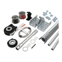
ONE SPRING SYSTEM
Right Hand
Drum (Black)
Set
Cone
End
Bearing
Support
Fig. 6
Left Side
Drum (Red)
Torsion
Tube
Left Side Wind
-
ing Unit (Green
Label)
Left Side Torsion
Spring (L-GREEN)
 Loading...