Do you have a question about the Clopay EZ-SET and is the answer not in the manual?
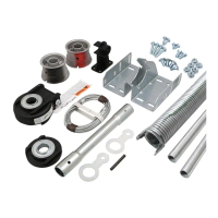
Lists the required tools for installing the EZ-SET Torsion Spring System.
Explains the meaning of the safety symbol indicating potential personal injury or property damage.
Attach brackets to the flag bracket and horizontal angle using carriage bolts and flange nuts.
Insert torsion tube sections into the coupler and secure with sheet metal screws.
Measure and record the relaxed length of each torsion spring on a flat surface.
Slide springs, drums, winding units, and end bearing support onto the torsion tube.
Connect the spring plug to the winding unit, ensuring color codes and tabs engage securely.
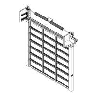
Lift and place the assembled torsion tube into the wall brackets, ensuring proper seating.
Attach center support to header for doors over 10' wide, ensuring tube is straight.
Install 1/4" insert bit or 7/16" socket in drill; set to forward rotation.
Adjust spring length to recorded value and tighten set screws securely. Avoid overstretching.
Insert cable lugs into drum slots and secure drums to torsion tube with set screws.
Attach tube retainers to the system brackets on both left and right sides.
Wind springs to specified number of turns, adjust tension by lifting door.
The EZ-SET® Torsion Spring System is a garage door spring assembly designed for use with standard garage door installation manuals. It provides the necessary spring tension for opening and closing garage doors.
The system utilizes torsion springs mounted on a torsion tube to counterbalance the weight of the garage door. As the door is lowered, the springs wind up, storing potential energy. When the door is raised, the springs unwind, releasing this energy to assist in lifting the door. This design ensures smooth and balanced operation of the garage door. The system is designed to be installed in conjunction with existing garage door tracks and hardware, with specific instructions for integrating the EZ-SET® components.
| Brand | Clopay |
|---|---|
| Model | EZ-SET |
| Category | Garage Door Opener |
| Language | English |