| 7
Nozzle
The nozzle assembly is located at the end of the sprayer. It is
composed of a spring-loaded contact, external O-ring, nozzle
cover, liquid tip and electrode. These are the only user-serviceable
components. To access the nozzle components, unscrew the nozzle
cover counterclockwise by hand. It is very important to follow all the
maintenance and cleaning procedures to ensure that the sprayer will
function optimally. After servicing nozzle, it is extremely important to
return the nozzle to its seat position and avoid overtightening.
NOTE: As the sprayer becomes dirty from typical use, a 70% isopropyl
alcohol cleaner that is manually applied is recommended on the
outside surfaces. This discourages dripping from the nozzle.
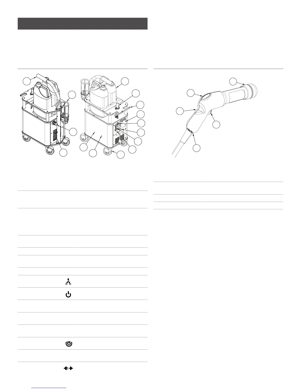
Clorox Total 360™ Base Unit
1
2
3
7
8
9
11
12
10
13
15
4
5
6
14
1 Air Compressor Atomizes and propels the liquid. Runs
on 115-volt power. Includes built-in
auto resetting thermal safeguard
against compressor overheating.
2 Non-Marking Wheels Large wheels, for easy transport and
maneuverability, will not leave scuff
marks. Do not require inflation.
3 Sprayer Connect Line Connect line consists of four
components: electrical line, liquid line,
air line and stainless steel braided
cable. The connect line connects the
sprayer to the base unit.
4 Air Filter User-replaceable air filter that filters
out particles from incoming air.
5 Sprayer Holster Holds the sprayer.
6 Adjustable Handle Handle position is raised, lowered and
rotated by the two button snaps.
7 Peristaltic Pump Provides liquid up to sprayer.
8 Circuit Breaker User resettable circuit breaker and will
only trip if a short occurs in the base unit.
9 Main Power
Switch
Powers system to a ready state.
10 1-Gallon Chemical
Containers
Chemical containers (not included
with equipment).
11 Extension Cord Holder Located at the rear of the unit for
extension cord storage.
12 Frame Stainless steel frame and hardware
design for long-term durability.
13 Pump Purge
Switch
Purges product from liquid line.
(press to purge)
14 Handle Adjust
Buttons
Adjusts handle height.
(squeeze to adjust)
15 Sprayer Electrical
Disconnect
Electrical connection for Sprayer.
Clorox Total 360™ Sprayer
1
5
2
4
3
1 Trigger Button 1-click functionality / operates the
sprayer/device.
2 Instrument Panel Indicates the power, sprayer and
electrostatics are on.
3 Nozzle Cover Located on the front of the sprayer.
4 Sprayer Grip Handle position for ambidextrous use.
5 Sprayer Connect Connect line consists of four components,
electrical line, liquid line, air line and
stainless steel braided cable.
SYSTEM COMPONENTS
The patented Clorox Total 360™ Electrostatic Sprayer was engineered
with the end-user in mind. It is a durable, highly mobile and incredibly
effective for electrostatic delivery.