CV Series Digital Amplifiers v1.0
7
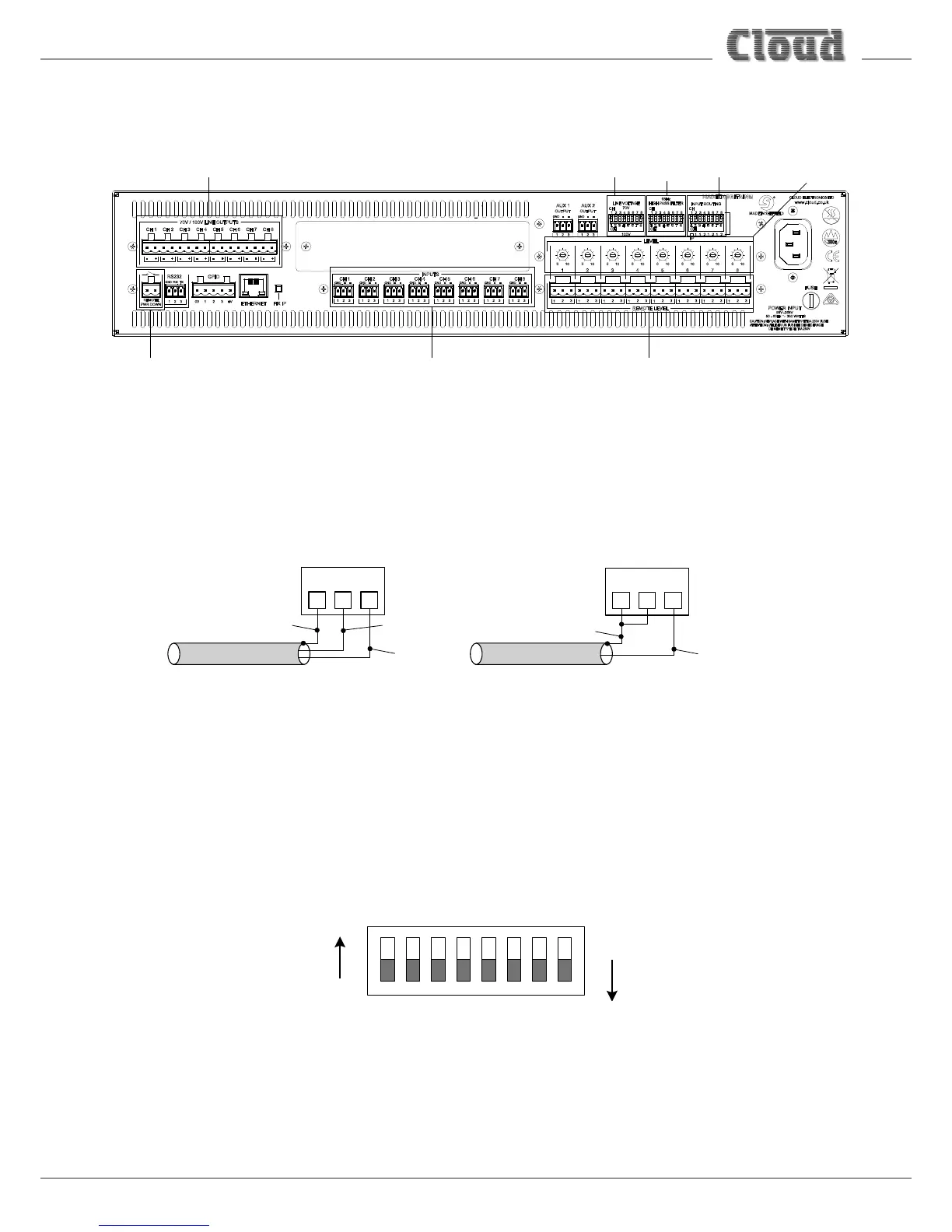
Connections and adjustments
INPUT CONNECTORS
REMOTE POWER DOWN
CONNECTOR
REMOTE LEVEL CONTROL CONNECTORS
OUTPUT
CONNECTORS
70/100 V
SWITCHES
AMPLIFIER PRESETS
INPUT ROUTING
SWITCHES
HIGH PASS FILTER
SWITCHES
Inputs
The amplifier inputs are balanced. Each channel uses a separate 3-pin, 3.5 mm-pitch screw-terminal connector. Connect as
shown below:
1
3
2
INPUT: BALANCED
CONNECTION
scn
scn
cold (-)
hot (+)
1
3
2
INPUT: UNBALANCED
CONNECTION
- +
OUTPUTS
to additional
loudspeakers
+ -
+ - + -
hot (+)
Outputs
The amplifier outputs can drive 100 V line or 70 V line loudspeaker systems directly. Check the 70V / 100V DIP switches to
ensure that they are in the correct position for the system voltage: there is one switch for each channel. (Note that on the
CV6160, switches 7 and 8 are not used.)
1 82 3 4 5 6 7
CH
100 V line
70 V line
(CV8125 shown as an example)
CV8125 8-Channel Digital Amplifier (shown as an example).
Other CV models with fewer channels provide the same
functionailty as the CV8125.