CX-A4 INSTALLATION AND OPERATION MANUAL 7
12 Bose
Equalisation Modules
Each channel on the CX-A4 can have Bose
equalisation so that its output will be
compensated correctly for a wide range of Bose
speakers.
Available Equalisation Modules:
- Bose
®
Speaker models: M8, M16, M32, MA12, 402, 502A, 502B, 502BEX,
802, MB4, MB24, LT3202, LT4402, LT9402, LT9702
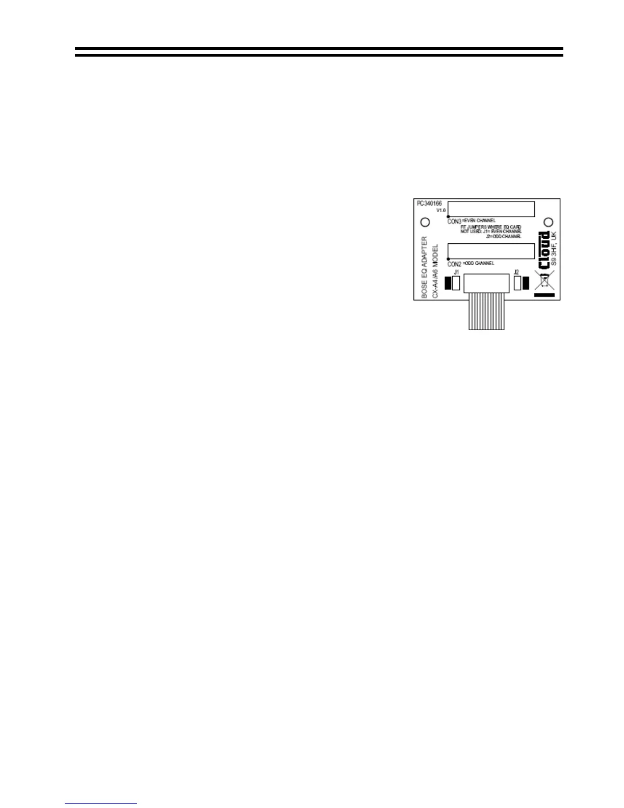
Bose
equalisation modules must be fitted to a stereo
EQ card adapter, Cloud part CA340166.The adapter is
a stereo fitting, so will cover two adjacent channels of
the amplifier. An equalisation module is required for
each channel that is to be equalised, and it is possible
to equalise a single channel using this module.
Note:
An EQ card adapter module cannot be installed to a
pair of channels with a VCA module installed.
13 Installing Optional Modules
There are three optional modules for the CX-A4; the VCA-2, the CA340166 Stereo EQ
card adapter for Bose
equalisation modules, and Bose
equalisation modules.
Components supplied with the various modules are listed below:-
VCA-2: Two 40mm M3 hex spacers, one plastic insert & two 3-pin screw terminal plugs.
CA340166 Stereo EQ card adapter: Two 25mm M3 hex spacers.
Bose
equalisation modules: No additional components.
The CX-A4 connectors to install the VCA modules are to the rear of the amplifier on the
input PCB clearly marked on the PCB as ‘CON X TO VCA MODULE’ where ‘X’ is 1 or 2
see below: -
CON 1 = Channel 1&2
CON 2 = Channel 3&4
Follow the instructions below carefully when installing modules. Incorrect installation can
cause damage.
1. Turn the power off and remove mains cable.
2. Remove the top panel.
3. Select the CX-A4 connector you wish to install the module to (see notes above) and
remove the jumpers from it.
4. When installing a VCA-2, remove the relevant rear panel blanking plate.
5. When installing a VCA-2, push the plastic plug into the rear panel ‘clip protect’ hole.
6. Two M3 fixing screws can be found adjacent to the CX-A4 connector. Remove and
retain these two screws then fix the M3 hex spacers in their place.
7. Push the 10-way plug onto the CX-A4 connector with the plug aligned so the cable
approaches it from the rear of the chassis and check that the connector mates with all
10 pins (important orientation diagrams can be seen on the following page).
8. When installing a VCA-2, position the 3-pin sockets and switch of the VCA through the
cut-outs in the rear panel.
9. Align the two holes in the module over the top of the two spacers.
10. Secure the module with the two M3x6 screws (removed earlier).
15-01-09 V10.0