Do you have a question about the Club Car Carryall 295 and is the answer not in the manual?
| Towing Capacity | 1, 000 lbs |
|---|---|
| Power Source | Gasoline |
| Transaxle | Differential |
| Parking Brake | Mechanical |
| Frame | Steel |
| Body | Polyethylene |
Lists safety statements to be heeded during vehicle operation, repair, or service.
Provides a step-by-step procedure to disable the vehicle before servicing or repair.
Details the procedure for disconnecting the battery, emphasizing safety precautions.
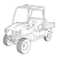
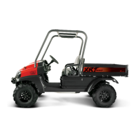
Lists detailed specifications for various vehicle models including power source, chassis, and dimensions.
Lists specifications for diesel vehicles, covering engine, fuel, ignition, and chassis details.
Lists specifications for the Intellitach model, covering power source, steering, and dimensions.
Provides instructions for safely storing the vehicle, including safety precautions for fuel and batteries.
Provides essential safety warnings and procedures for lifting the vehicle, including jack stand usage.
Explains the safe and correct procedure for jump-starting the vehicle using a booster battery.
Provides safety warnings regarding the ROPS and outlines its removal procedure.
Provides general warnings and cautions regarding the proper care and function of safety belt systems.
Explains how to adjust the accelerator pedal and engine RPM for early 2010 models.
Details inspection of brake discs for warping and brake pads for wear and contamination.
Provides a guide for diagnosing and correcting common brake system issues based on symptoms.
Covers procedures for removing and installing front and rear brake pads and calipers.
Covers removal and installation of brake discs for models starting in 2012.
Provides procedures for replacing hydraulic brake lines, including warnings about bleeding the system.
Covers inspection, filling, removal, and installation of the master cylinder and reservoir.
Explains the specific procedure for bleeding hydraulic brakes using DOT 5 fluid, including vacuum and manual methods.
Covers park brake adjustment procedures and front park brake cable adjustments.
Explains wheel alignment, including toe-in and camber adjustments, and inspection for wear.
Details lubrication intervals and recommended lubricants for various vehicle components.
Provides critical safety warnings and procedures for fueling the vehicle, covering gasoline and diesel.
Presents wiring diagrams for gasoline utility vehicles, showing front and rear electrical systems.
Lists and describes various test procedures for electrical components and systems.
Explains how to test the starter control circuit, including checking voltage at the starter solenoid.
Outlines the procedure for testing the start relay, including checking voltage and continuity.
Details testing the neutral switch on the transmission for continuity in different gear positions.
Covers testing the front differential limit switch, checking for continuity with accelerator pedal movement.
Covers testing the bed lift motor by checking voltage readings with the switch in UP and DOWN positions.
Provides a guide for identifying operating difficulties in diesel vehicles, including symptoms, causes, and checks.
Lists possible causes and references for troubleshooting when the starter motor functions but the engine does not start.
Identifies potential causes for an engine not running smoothly and directs to relevant troubleshooting sections.
Lists possible causes for loss of engine power and directs to relevant troubleshooting sections.
Details common causes for engine overheating and recommended actions.
Details procedures for testing the battery, including hydrometer and voltage tests, with safety warnings.
Details the procedure for testing fuses using a multimeter, including safety warnings about fuse replacement.
Covers testing the key switch for the starter circuit, checking continuity in different positions.
Details testing the starter control circuit, including checking voltage at the starter solenoid.
Covers testing the fan relay for power, function, and continuity.
Details testing the thermostat switch for continuity under different temperature conditions.
Details testing in-line diodes in the wire harness for proper function using a multimeter.
Details the process for removing the diesel engine, including disconnecting components.
Covers fuel system components like lines, filter, pump, and tank, with maintenance info.
Covers clutch troubleshooting, drive belt service, drive clutch, driven clutch, and clutch cover procedures.
Explains the procedure to relieve hydraulic pressure before disconnecting components, with safety warnings.