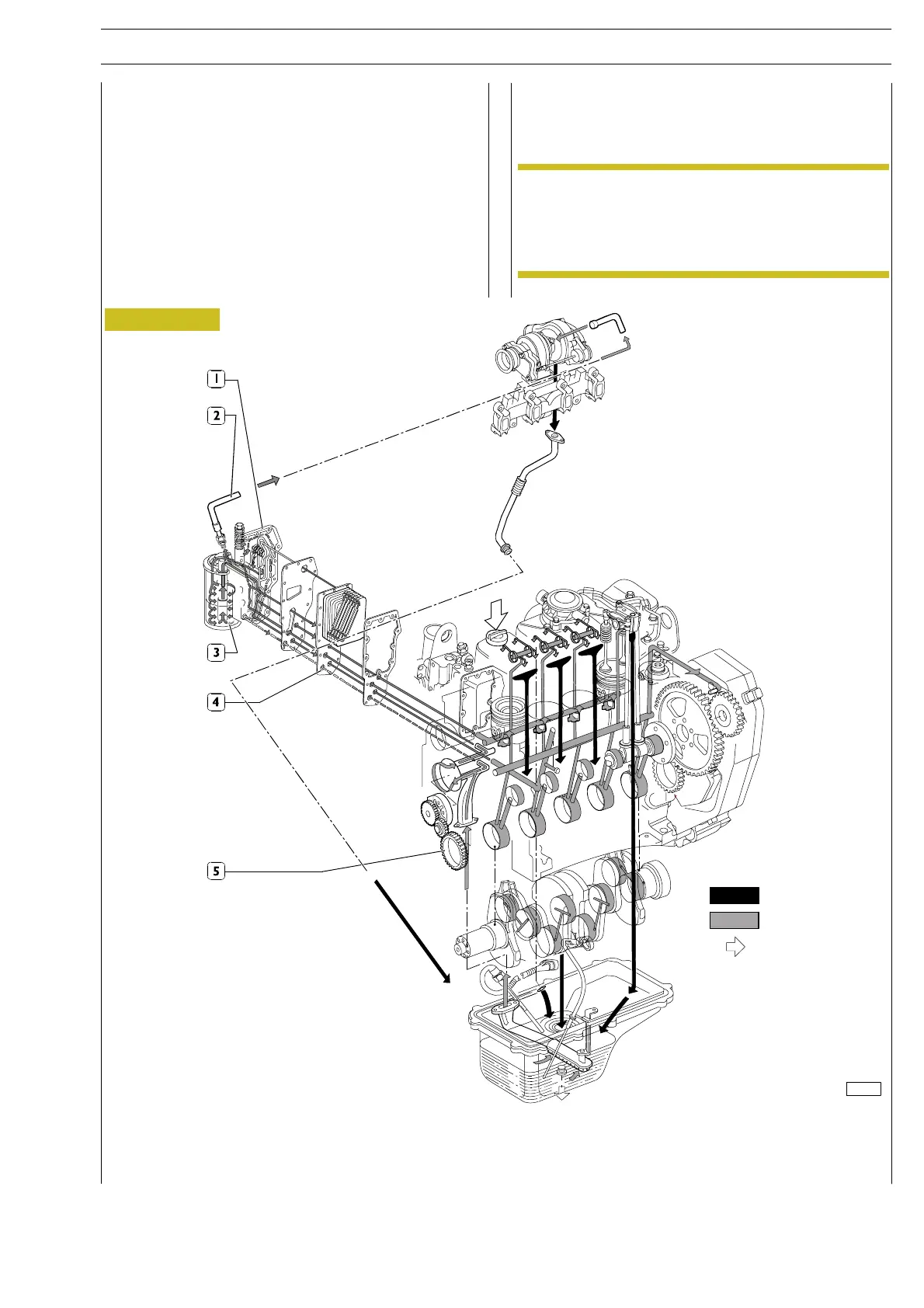
Figure 3
LUBRICATION
Lubrication by forced circulation is achieved through oil rotary
expansion pump, placed i n the front part of the basement,
driven by the straight-tooth gear splined to the shaft’s bar hold.
From the pan, the lubrication oil flows to the driving shaft, to
the camshaft and to the valve drive.
Lubrication involves the heat exchanger (2,3), the
turboblower for turbocompressed versions, and for any
compressed air system.
All these components may often vary according to the specific
duty.
LUBRICATION SYSTEM LAYOUT
1. Heat exchanger body - 2. Lubrication oil pipe to supercharger - 3. Oil filter - 4. Heat exchanger -
5. Oil rotary expansion pump.
116396
Routing of oil unde
pressure
Routing of oil return
by gravity to sump
Introduction of oil
Some groups can be located on the engine in
different positions due to requirements dictated by
the application, and have variable shapes and
dimensions depending upon the use and the
versions of the engine itself.
NOTE
SECTION 1 - GENERAL SPECIFICATIONS 5
NEF ENGINES