5
ENGLISH
14
6
16
18
19
10
20
21
fig. 3
fig. 4
fig. 5
fig. 6
17
9. Belt tilt locking screw
10. Belt frame
11. Foot
12. Fastening hole
13. Power switch ON/OFF
14. Sanding disc guard
15. Side table
3. Assembly and preparations
Warning! Always make sure that the mains lead is unplugged before assembling or servicing/adjusting
the machine.
The sanding belt and disc are ready mounted at the factory.
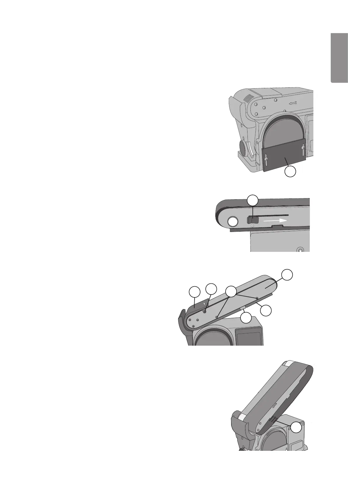
3.1 Fitting/changing sanding disc paper (fig. 3)
1. Unplug the sander.
2. Remove the adjustable side table.
3. Undo the two screws holding the disc guard (14)
and remove the guard.
4. Remove the old sanding disc paper.
5. Peel the protective film off the new sanding disc
paper.
6. Align the new disc paper on the disc pad making
sure that it is centred. Press the sanding disc
paper firmly onto the disc pad.
7. Screw the guard (14) back into place.
3.2 Fitting/changing the sanding belt (fig. 4, 5, 6)
1. Unplug the sander.
2. Unscrew the work stop (3).
3. Move the release lever ((6) in fig. 4) in the direction
of the arrow to release the roller so that the
sanding belt can be removed.
4. Remove the two screws ((16) in fig. 5) on both
sides of the belt frame (10). Remove the upper
guard ((17) in fig. 5).
5. Remove the four screws ((18) in fig. 5) on both
sides of the belt frame (10). Remove the lower
guard ((19) in fig. 5).
6. Remove the rubber snubber ((20) in fig. 5).
7. Remove the old sanding belt from the rollers.
8. Fit the sanding belt the right way round.
The new sanding belt has an arrow on the inside
((21) in fig. 6), the belt must rotate in the direction
indicated by the arrow. Make sure that
the sanding belt is centred on both the rollers.
9. Replace the rubber snubber, upper guard and
lower guard. Tighten the screws on the side of
the belt frame.
10. Move the release lever ((6) in fig. 4) forwards to
tension the belt.
11. Adjust the belt tracking.
Warning! The release lever is spring-loaded,
be careful when moving it.
 Loading...