6
ENGLISH
9
22
107
1010
7
fig. 7
fig. 8
fig. 9
fig. 10
fig. 11
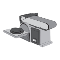
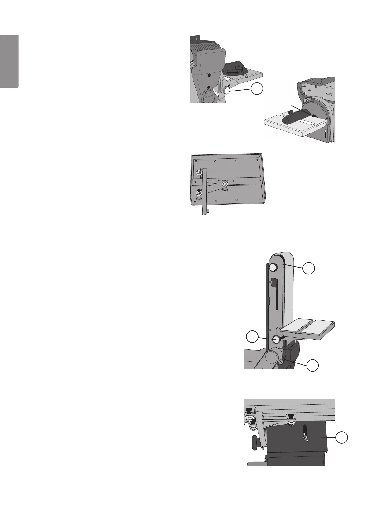
3.3 Mounting the side table (fig. 7, 8, 9)
1. Unplug the sander.
2. Insert the side table guide pin (on top of the
bracket) into the hole in the frame.
3. Tighten the locking knob ((7) in fig. 7).
4. To adjust the table: Undo the three screws on the
bottom of the side table (fig. 9). Adjust the side
table so that the distance between the table and
belt is no more than 1–2 mm (fig. 8).
Tighten the screws and the locking knob.
Warning! The distance between the sanding belt and
table must be no more than 1 or 2 mm otherwise
there is the possibility of fingers becoming trapped
in the gap.
3.4 Using the side table for belt sanding (fig. 10, 11)
1. Unplug the sander.
2. Unscrew the work stop (3).
3. Undo the locking screw (9), raise the belt frame
(10) and then tighten the locking screw.
4. Insert the side table guide pin (on top of
the bracket) into the hole in the frame.
5. Tighten the locking knob ((7) in fig. 10).
6. To adjust the table: Undo the three screws on the
bottom of the side table (fig. 9). Adjust the side
table so that the distance between the table and
belt is no more than 1–2 mm. Tighten the screws
and the locking knob.
Warning! The distance between the sanding
belt and table must be no more than 1 or 2
mm, otherwise there is the possibility of fingers
becoming trapped in the gap.
7. Adjust the moveable guard ((22) in fig. 11) so that
it covers the sanding belt beneath the table.
max. 2 mm
 Loading...