speak clearly in a normal "voice". The radios come complete with a
low-impedance 500-
ohm
dynamic microphone. For installation instruc-
tions on
other
microphones, see next section, "ALTERNATE MICRO-
PHONES AND INSTALLATION.''
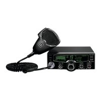
B.
INDICATOR
FUNCTIONS
S-METER.
Swings proportionally
to
the strength
of
the incoming signal.
RF
METER.
Swings proportionally to the
RF
output
power. When
transmitting, the RF
-% MOD switch must be in the
"RF"
position and the
OFF-CAL-SWR switch must be in the
"OFF"
position.
MODULATION
METER.
Swings proportionally to the degree
of
modula-
tion. When transmitting, the RF
-%
MOD
switch must be in the %
MOD
position, and the OFF-CAL-SWR switch must be in
the
"OFF"
position.
SWR
METER.
Measures the ratio
of
standing wave voltage
of
the antenna
system. Used to properly adjust the length
of
the antenna, and
to
monitor
the quality
of
the coaxial cable and
all
RF electrical connections.
If
there
is
any degradation whatsoever in any
of
the above, due to humidity, salt
spray, vibration or corrosion. the SWR meter reading will rise, thereby
indicating
that
a problem exists.
To calibrate, switch
to
the
"CAL"
position transmit
by
pressing the mike
switch, and adjust the SWR control to the
"CAL"
mark on the meter then
switch
to
"SWR"
position for the SWR measurement.
CHANNEL
INDICATOR.
The selected channel appears on the LED readout
directly above the channel selector knob .
C.
OPERATING
PROCEDURE
TO
RECEIVE
1.
Place the CB/PA switch in the
CB
position.
2. Turn the set ON by turning the VOLUME control clockwise, until a
click
is
heard.
3. Set the VOLUME for a comfortable listening level.
17