Do you have a question about the Coda Linus 10 and is the answer not in the manual?
General usage and safety recommendations for the amplifier, including adherence to manual guidelines.
Emphasizes reading and keeping the user manual for safe operation and potential resale.
Guidelines for secure mounting to prevent falling and damage, using manufacturer-recommended accessories.
Requirement to connect only to a socket with a protective earth connector.
Prohibition of exposure to rain, moisture, or placing liquids on the unit.
Ensuring ventilation slots are not blocked for proper operation and to prevent overheating.
Warning against inserting objects into openings to avoid electric shock or damage.
List of situations (liquid spill, damage, cord damage) that require professional service.
All servicing and repair work must be performed by authorized dealers or qualified personnel.
Symbol indicating high voltage hazards and warning against opening the unit.
Symbol alerting to high voltage hazards within the product, requiring authorized service.
Symbol indicating high voltage at output connectors that could be life-threatening.
Symbol warning to prevent fire or shock hazard by not exposing to rain or moisture.
Symbol indicating the amplifier must be connected to a socket with a protective earth conductor.
Connecting the amplifier to an appropriate AC circuit using specified mains cables.
Explanation of the special processor dedicated to limit the mains inrush current.
Table detailing mains current draw and power consumption at various operating conditions.
Details on connecting speakers using SPEAKON connectors, including wiring configuration.
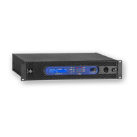
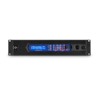
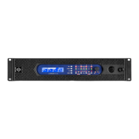
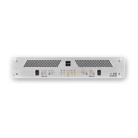
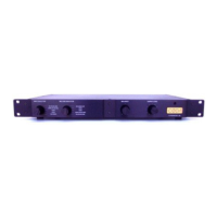
Overview of the front panel display, buttons, and navigation for operating the amplifier.
Adjusting the input gain level for selected amplifier channels.
Adjusting the output gain level for selected amplifier channels.
Accessing and adjusting tuning parameters, including array, sizing, and full parametric EQ.
Detailed description of front panel LEDs for status monitoring and troubleshooting.
Overview of internal protection mechanisms like SOA, DC, and Overcurrent protection.
Protection features related to the AC power supply, including overvoltage and failure detection.
Limits average input current to prevent external mains breaker tripping during high output.
Protection features for the Switched Mode Power Supply, including overcurrent and thermal monitoring.
Specifications for output power at various impedance loads (16, 8, 4, 2 Ohms).
Specifications for peak output power at different impedance loads.
Specification for the signal-to-noise ratio (SNR) of the amplifier.
Power consumption figures for standby, idle, and various output levels at 230V.
Specification for the amplifier's frequency response across a range of frequencies.
Specification for Total Harmonic Distortion plus Noise over the frequency range.
Summary of various protection circuits integrated into the amplifier.