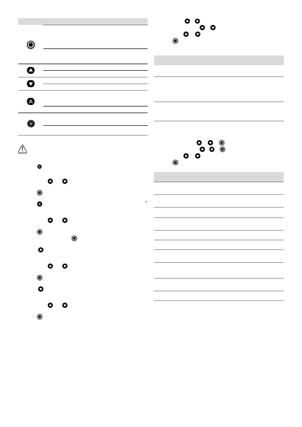
3
P-BUTTON TOUCH ACTION
click!
From state ON: unit OFF.
From state OFF: the pump starts and keeps opera-
ting until reaching Pstop.
From any conguration MENU: the parameter
value is accepted.
HOLD
DOWN
From state ON: unit OFF.
From state OFF: the pump starts and keeps opera-
ting until the push-button is released.
click! Pstart is displayed on the screen for 3 seconds.
3” Pstart adjustment mode.
click! Pstop is displayed on the screen for 3 seconds.
3” Pstop adjustment mode.
click!
Is displayed on the screen instantaneous current
consumption.
If it is already displayed then we switch to instanta-
neous pressure view.
3” Rated current adjustment.
click!
Is displayed on the screen instantaneous voltage.
If it is already displayed then we switch to instanta-
neous pressure view.
3”
Adjust rated voltage between dierent options:
110V, 125V, 220V, 230V, 380V, 400V.
STARTUP
Before starting the device please read the previous sections, espe-
cially “Hydraulic Installation” and “Electrical connection”.
Follow next steps:
1. Set the power supply voltage.
- Press
during 3 seconds.
- The voltage value is displayed on screen, LED V lights up and display
is ashing.
- By mean of
and is adjusted the power supply voltage. See
Note 1.
- Press
for validation.
2. Set the pump rated current intensity value.
- Press
during 3 seconds.
- The current intensity value is displayed on screen, LED A lights up and
display is ashing.
- By mean of
and is adjusted the rated current reected in the
characteristics plate of the motor. See Note 2.
- Press
for validation.
3. Start the device by pressing
.
4. Set the cut-in (start) pressure:
- Press
during 3 seconds.
- The start pressure value is displayed on screen, LED START lights up
and display is ashing.
- By mean of
and is adjusted the start pressure from 0,5 to 11,5
bar (+ version=11 bar).
- Press
for validation.
5. Set the cut-out (stop) pressure:
- Press
during 3 seconds.
- The stop pressure value is displayed on screen, LED STOP lights up
and display is ashing.
- By mean of
and is adjusted the stop pressure from 1 to 12 bar
(+ version=12 bar).
- Press
for validation.
6. The unit is ready to operate but more optional adjustments can be set
through basic and advanced MENUS. See the next chapter.
Remark 1: it is important to introduce exactly the power supply
voltage specied on the nameplate of the pump.
Remark 2: it is important to introduce exactly the rated current
specied on the nameplate of the pump.
BASIC MENU +
- Press simultaneously + during 5 seconds.
- By mean of
or the values can be changed.
- Press
for validation.
- The parameters sequence is:
it TYPE SYSTEM REACTION
FACTORY
SETTING
1 BAR P
We can select the pressure units displayed
beetween bar and psi.
bar
2 rc0 rc2
Fast-cycling alarm:
- rc0: alarm unabled.
- rc1: activated, when hammering is detected
it is delayed the start in order to protect
the pump.
- rc2: alarm is activated and the pump is stop-
ped upon detection.
rc2
3 r.01 r.99
Only if fast-cycling alarm has been activated in
the previous step (rc1&rc2). It can be choosed
the maximum time period between 3 consecu-
tive starts that will be considered fast cycling
(between 1 sec. and 99 sec.)
3 se-
conds
4 Sb0 Sb1
Stand-by mode activated (Sb1), for low power
consumption, or unabled (Sb0).
Sb0
ADVANCED MENU + +
- Press simultaneously + + during 5 seconds.
- By mean of
or the values can be changed.
- Press
for validation.
- The parameters sequence is:
it TYPE SYSTEM REACTION
FACTORY
SETTING
1 nc no
Select the operation MODE as a conventio-
nal pressure switch (nc = normally closed) or
reverse (no = normally open). *see remark 3
nc
2 E00 E01/02
Select the operation mode Individual (E00)
or Master/Slave (E01/E02) in case of be
assembled in groups of two pumps.
E00
2.1 d.05 d.1
Sets the minimum gap between Pstart 1 and
Pstart 2 and/or Pstop 1 and Pstop 2.
d.05
3 ct0 ct9
Sets a time delay between 0 and 9 seconds
to the start (is not available in synchronized
operation mode).
ct0
4 dt0 dt9
Sets a time delay between 0 and 9 seconds
to the stop.
dt0
5 Ar0 Ar1
Activation of the automatic restore system
ART (Ar1) o disable (Ar0).
Ar0
6 P0.0 Px.x
It allows setting a minimum operating
pressure under which the device would
determine dry-running operation.
0 bar
0 psi
6.1 t05 t99
Set the time period between 5 and 99
seconds below the minimum operating
pressure that will be considered a dry-
running operation.
20”
7 c10 c30
It allows setting a % of nominal current
above which the device will activate the
overcurrent protection.
c20
8 rS0 rS1
If we change rS0 to rS1 and push ENTER
default values are restored.
rS0
Remark 3:
By choosing “no” (normally open) it will operate as an auxiliary
pressure control element in the suction of the pump. It will restart
when the suction pressure reaches the congured PStart.
Example:
- PStop: 0,9 bar
- PStart: 1,2 bar
 Loading...